Installation – Advanced Protection XGA User Manual
Page 7
7
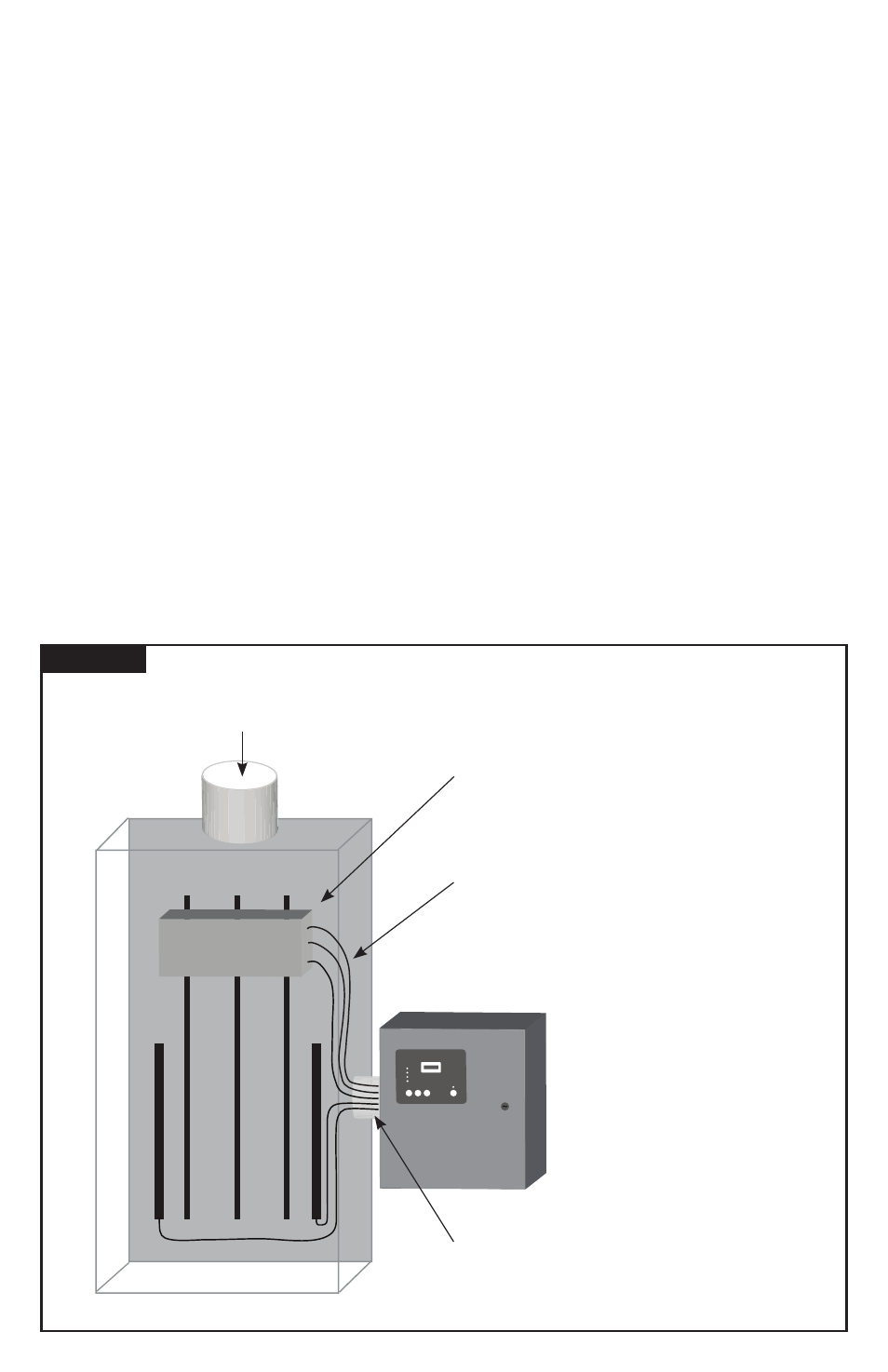
Figure 7
TYPICAL PANEL INSTALLATION
A
B
C
G
N
BREAKER
Phase C
Service
Phase B
Phase A
Surge Counter
Advanced Protection Technologies
Silence
Test
Count
Reset
To Protected Loads
▪
Use closest breaker to SPD
▪
Locate SPD close to intended breaker
▪
Keep Leads Short as Possible
▪
Avoid Sharp Bends
▪
Outdoor installation requires appropriate
weather sealing at nipple (o-ring, sealing
conduit, etc.)
INSTALLATION
Common Problems to Avoid
▪
Confirm System voltage to SPD voltage (120V SPD will fail instantly on 240V, 277V, etc.).
▪
Locate SPD close so leads are short & straight as possible (or will seriously hurt performance).
▪
Make sure N-G or XO bonding meets NEC
®
(or will prematurely fail SPD).
▪
Energize SPD AFTER system is stabilized & checked (inadvertent system problem may fail SPD).
▪
SPDs are regulated by NEC
®
Article 285 and UL 1449.
▪
Never Hi-Pot test any SPD (will prematurely fail SPD).
Pre-Plan your installation.
You will need to accomplish the following:
▪
Meet all National and Local codes (NEC
®
Article 285 addresses SPDs).
▪
Mount SPD as close to panel or equipment as possible to keep leads short.
▪
Ensure leads are as short and straight as possible, including neutral and ground. Consider a breaker position that
is closest to the SPD and the panel’s neutral & ground.
▪
Suggested breaker & conductor size is 60A-30A with 6 AWG (60A preferred).
▪
Make sure system is grounded per NEC
®
and clear of faults before energizing SPD.
1. Use a voltmeter to check all voltages to ensure correct SPD.
2. If SPD has Dry Contact, Remote Monitoring or Remote Display, pre-plan their installation
3. Remove power for panel. Confirm panel is deenergized.
4. Identify breaker location and SPD location.
5. Make sure leads are short! Reducing inches matters! Pretend that connector leads cost you $1000 per foot!
6. Remove an appropriately sized knockout from panel. Create an appropriately sized hole in the SPD enclosure.
7. Mount SPD.
8. Connect conductors as appropriate – short and straight as possible (Note that Hi-Legs are Phase B).
9. Label or mark conductors as appropriate (neutral: white, ground: green, energized: black, hi-leg: orange).
10. Make sure system is bonded per NEC
®
and is clear of hazards or faults before energizing (N-G bonding not per
NEC
®
will fail SPDs: #1 cause of SPD failures).
11. Energize and confirm proper operation of indicators and/or options.