West Control Solutions KS 800 ISO1745 Interface Manual User Manual
Page 16
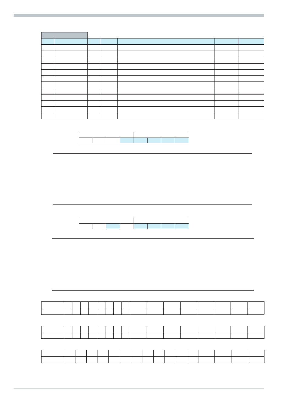
I/O connection
(Function no.: 2)
Code Des.
R/W Type
Description
Range
Rem.
0
Block 1...2
R
Block
1
State_alarm_out R
ST1
Status alarm outputs
G
2
State_dio
R
ST1
Status digital inputs/outputs
H
20
Block 21...24
L
Block
21
SnOEMOpt
L
INT
Seriennummer OEM-Feld
22
SnFabMonth
L
INT
Seriennummer Fabrikationsmonat
23
SnCntHi
L
INT
Seriennummer Zähler High
24
SncntLo
L
INT
Seriennummer Zähler Low
30
Block 31...33
L
Block
31
Fdo1
L/S ICMP Forced digitale Ausgänge: OUT1 ... OUT8
J
32
Fdo2
L/S ICMP Forced digitale Ausgänge: OUT9 ... OUT16
K
33
Fdo3
L/S ICMP Forced digitale Ausgänge: OUT17 ... OUT19
L
Bem. H State_alarm_out
MSB
LSB
D7
D6
D5
D4
D3
D2
D1
D0
Bit no.
Name
Allocation
Status ‘0’
Status ‘1’
D0
R1
Relay 1
off
on
D1
R2
Relay 2
off
on
D2
R3
Relay 3
off
on
D3
do1_12 AL
Alarm output short circuit do1 ... do12
off
on
D4
HCscAL
Alarm message heating current short circuit off
on
D5
‘0’
Always ‘0’
D6
‘1’
Always ‘1’
D7
Parity
Bem. I State_dio
MSB
LSB
D7
D6
D5
D4
D3
D2
D1
D0
Bit no. Name
Allocation
Status ‘0’
Status ‘1’
D0
Par_Nr
Parameter set number
set 0
set 1
D1
w/w2
w/w2 switch-over
w
w2
D2
Coff
Controller off
off
on
D3
Leck
Leakage current
off
on
D4
‘0’
Always ‘0’
D5
do13_16f
do13 ... do16 Fail
no
yes
D6
‘1’
Always ‘1’
D7
Parity
Bem. J Aufbau der Datenstruktur
Bit
15 14 13 12 11 10 9 8
7
6
5
4
3
2
1
0
Bedeutung 0 0 0 0 0 0 0 0 OUT8 OUT7 OUT6 OUT5 OUT4 OUT3 OUT2 OUT1
Bem. K Aufbau der Datenstruktur
Bit
15 14 13 12 11 10 9 8
7
6
5
4
3
2
1
0
Bedeutung 0 0 0 0 0
0 0 0 OUT16 OUT15 OUT14 OUT13 OUT12 OUT11 OUT10 OUT9
Bem. L Aufbau der Datenstruktur
Bit
15 14 13 12 11 10
9
8
7
6
5
4
3
2
1
0
Bedeutung
0
0
0
0
0
0
0
0
0
0
0
0
0
OUT19 OUT18 OUT17
Function block protocol
9499 040 49411
16