Thermo Fisher Scientific CyberScan pH 1000/pH 2500 User Manual
Page 11
Instruction Manual
pH 1000/ 2500
6
4
STARTING UP THE METER
4.1
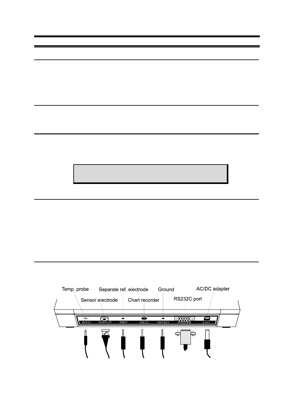
Connecting the Sensor Electrode
Slide the sensor electrode connector of the electrode over the INPUT BNC socket. Then push the
connector into the socket and turn the connector clockwise to lock into position. Do not use excessive
force. This applies to combination pH/ORP/ISE electrodes. For half-cell sensors where a reference
electrode is used, connect the sensor connector to socket marked (REF). Always ensure that the
connectors are dry when connection is done.
4.2
Connecting the Temperature Probe
The temperature probe uses a phono jack to connect with the socket marked ATC on the meter. Insert
the jack directly into the socket until it is firmly seated.
4.3
Connecting the AC/DC Adapter
Ensure that the power to the AC/DC adapter is switched off. Slide the AC/DC adapter jack into the
socket marked DC of the meter until it is firmly seated. For AC/DC adapter always ensure that the
power mains voltage matches that of the adapter used. AC/DC adapters used should have the
following specifications or settings. Output:- Voltage: 9 V DC Current: 500 mA.
NOTE:
Ensure that the input power mains voltage (120/220 V)
matches your adapter requirements.
4.4
Connecting the Chart Recorder
The meter provides a recorder output of +/- 2000 mV for transmission of readings either to a chart
recorder or to a data acquisition device (Analog/Digital Cards). When the chart recorder is in
operation, continuous absolute mV readings will be charted. Note that readings are independent of the
operating mode and is uncompensated and set to a one to one (1:1) ratio.
Where the charting is made in reference to ground potential, a cable is connected from the GND port
of the meter to the chart recorder. Plug the phono connector to the meter at the designated port
(marked REC). The tip (inner) connection should be wired to the high side of the recorder and the
sleeve (outer) side should be wired to the low side of the recorder.
4.5
Connecting RS232C Cable
Noting the orientation of RS232C connector, insert the 9-pin male connector from your device (a
printer or computer) into the RS232C port (marked RS232) of the meter. Fasten the RS232C
connector using the two screws at the side of the male RS232C connector. Do not over-tighten.