Commands/r, Specifications, Calibration – SHIMPO FGV-series User Manual
Page 4: Response from fgv gauge, Commands to fgv gauge, Required for calibration, Calibration procedure, Error symbols, Shimpo instruments
4
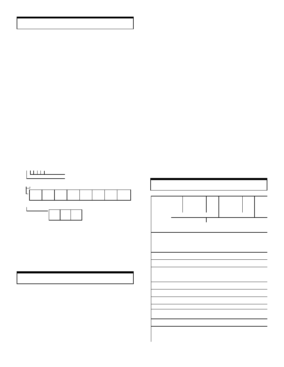
Response from FGV Gauge
NA!!!!!! cr:
Average data output
NB!!!!!!cr:
Peak data output
4-digit number with decimal point
sign (+ or –)
Commands/R
Commands/R
Commands/R
Commands/R
Commands/Responses
esponses
esponses
esponses
esponses
The FGV series of force gauges has the ability to recognize
and respond to various commands from outside peripherals. If
for instance the gauge receives a legitimate command from a
PC, it will respond by sending back the same code indicating
to the PC that the command was recognized. If for example the
command is a request for average data output, it will send the
data and the code NA etc. If the gauge recognizes an error
while it is receiving a command, an error symbol is transmitted
back to the PC indicating the exact nature of the error.
Commands to FGV Gauge
AAcr:
Tare
ABcr:
Stop output
ACcr:
Change to peak mode
ADcr:
Change to average mode
AEcr:
Peak reset
AFcr:
Change units to kg (g)
AGcr:
Change units to N
AHcr:
Change units to lb (oz)
BAcr:
Data output request
BBcr:
Continuous data output request (10 times/sec)
BCcr:
Model name confirmation request
BDcr:
Units confirmation request
BEcr:
Peak data output request
SHIMPO INSTRUMENTS
1701 Glenlake Avenue, Itasca, IL 60143 USA
"
#
(630) 924-7138 FAX (630) 924-0342
Specifications
Specifications
Specifications
Specifications
Specifications
MODELS
MODELS
MODELS
MODELS FGV-0.5
FGV-0.5
FGV-0.5
FGV-0.5
FGV-1
FGV-1
FGV-1
FGV-1
FGV-2
FGV-2
FGV-2
FGV-2
FGV-5
FGV-5
FGV-5
FGV-5
FGV-10
FGV-10
FGV-10
FGV-10
FGV-20
FGV-20
FGV-20
FGV-20
FGV-50
FGV-50
FGV-50
FGV-50
FGV-100
FGV-100
FGV-100
FGV-100
CAPACITY
CAPACITY
CAPACITY
CAPACITY
8 oz
200 g
2 N
16 oz
500 g
5 N
2 lb
1000 g
10 N
5 lb
2 Kg
20 N
10 lb
5 Kg
50 N
20 lb
10 Kg
100 N
50 lb
20 Kg
200 N
100 lb
50 Kg
500 N
RESOLUTION
RESOLUTION
RESOLUTION
RESOLUTION
0.01 oz
0.001 lb
0.01 lb
0.1 lb
0.1 g
1 g
0.001 Kg
0.01 Kg
0.001 N
0.01 N
0.1 N
ACCURACY
ACCURACY
ACCURACY
ACCURACY ±0.2% FS plus 1/2 digit at 73°F (23°C)
DISPLAY
DISPLAY
DISPLAY
DISPLAY 4-Digit LCD 12mm high. Reversible by a push of a button. Minus sign for tension.
AVERAGE/
AVERAGE/
AVERAGE/
AVERAGE/
PEAK MODE
PEAK MODE
PEAK MODE
PEAK MODE Yes (selectable)
LOW BATTERY
LOW BATTERY
LOW BATTERY
LOW BATTERY
INDICATION
INDICATION
INDICATION
INDICATION Yes
DISPLAY
DISPLAY
DISPLAY
DISPLAY
UPDATE
UPDATE
UPDATE
UPDATE 0.3 second
SAMPLING
SAMPLING
SAMPLING
SAMPLING
RATE
RATE
RATE
RATE 35 times per second
OVERLOAD
OVERLOAD
OVERLOAD
OVERLOAD 200% of FS
POWER
POWER
POWER
POWER Rechargeable Ni-Cad batteries or AC through adapter/charger
OUTPUT
OUTPUT
OUTPUT
OUTPUT RS232C and ±1VDC (through a 12 bit D/A converter)
AUTO POWER
AUTO POWER
AUTO POWER
AUTO POWER
OFF
OFF
OFF
OFF Yes (not active if adapter/charger is in use)
BATTERY
BATTERY
BATTERY
BATTERY
CHARGE
CHARGE
CHARGE
CHARGE 20 hrs. when fully charged
RECHARGE
RECHARGE
RECHARGE
RECHARGE
TIME
TIME
TIME
TIME
12 hrs. approx.
TEMPERATURE
TEMPERATURE
TEMPERATURE
TEMPERATURE 32° - 104°F (0° - 40°C)
DIMENSIONS
DIMENSIONS
DIMENSIONS
DIMENSIONS 5.1"L x 2.9"W x 1.5"H (130 x 75 x 38)mm
WEIGHT
WEIGHT
WEIGHT
WEIGHT 1lb (450g)
OVERLOAD
OVERLOAD
OVERLOAD
OVERLOAD
OUTPUT
OUTPUT
OUTPUT
OUTPUT
One NPN OC transistor for tension, one NPN OC transistor for compression
ACCESSORIES
ACCESSORIES
ACCESSORIES
ACCESSORIES
(INCLUDED)
(INCLUDED)
(INCLUDED)
(INCLUDED)
AC adapter/charger, carrying case, hook ,chisel, flat head, notched head, hanger,
cone head, extension rod and analog output cable.
ACCESSORIES
ACCESSORIES
ACCESSORIES
ACCESSORIES
AVAILABLE
AVAILABLE
AVAILABLE
AVAILABLE Test stands, RS232C cable, overload cable.
Calibration
Calibration
Calibration
Calibration
Calibration
Required for Calibration:
1. A secure calibration stand to mount a force gauge upside-
down.
2. The appropriate calibration weight for your force gauge:
Calibration Procedure:
1. Turn POWER off.
2. Mount the force gauge upside-down on the calibration stand.
3. Attach the hook on the sensing shaft of the force gauge.
4. Press and hold the UNIT, PEAK and ZERO switches.
5. Press and release the POWER switch (while continuing to
press UNIT, PEAK and ZERO) until the smaller characters
at the top area of the display show
CAL. Release the UNIT,
PEAK and ZERO switches. The force gauge is now in cali-
bration mode.
6. Press the UNIT switch. The display will show
ZER. The
force gauge is now ready for zero point calibration.
7. Press ZERO to zero point calibrate. Wait 5 seconds. The
display will change to show
PEK. Do not press any other
switches or move the sensing shaft during calibration.
8. Hang the calibration weight on the hook and stabilize; the
larger characters on the display will change. The force gauge
is now ready for full scale calibration.
9. Press the PEAK switch to begin full scale calibration. Do not
press any other keys or touch the weight during calibration.
After approximately 5 seconds the display will show
END.
10. Press the UNIT switch. If calibration was successful, the
display will show
OK momentarily, then automatically power
off. If calibration was unsuccessful, the display will show
ERR. Remove the calibration weight and repeat the proce-
dure from step 6.
MODEL WEIGHT
FGV-0.5 200g
FGV-1 500g
FGV-2 1Kg
FGV-5 2Kg
MODEL WEIGHT
FGV-10 5Kg
FGV-20 10Kg
FGV-50 20Kg
FGV-100 50Kg
02
03
04
05
06
07
08
09
FGV-0.5
FGV-1
FGV-2
FGV-5
FGV-10 FGV-20 FGV-50 FGV-100
0
1
2
N
Kg (g) lb (oz)
Error symbols:
OBcr:
Command error
ODcr:
Overload error
OEcr:
Parity error
OFcr:
Format error
OGcr:
Summing error
OHcr:
Overrun error
NH!cr:
Unit
NE!!cr:
Model number