Rs232c p, Connections, Dimensions – SHIMPO FGV-series User Manual
Page 3: Analog output
3
RS232C P
RS232C P
RS232C P
RS232C P
RS232C Port
ort
ort
ort
ort
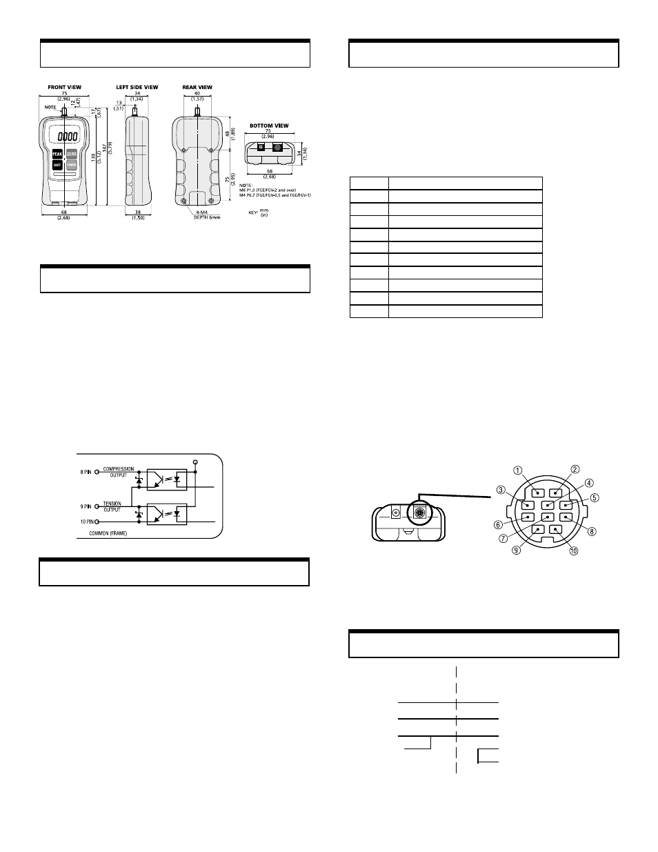
The most important feature of the FGV family of gauges is
the availability of the RS232C communications port. Data
and commands can be linked to a PC or any other device
responding to RS232C signals for storage or further analy-
sis. Table 1 (below) describes the function of each pin of
the connector (HR12-10RC-10SDL) shown in Fig. 3.
PIN#
DESCRIPTION
1
Analog signal output
2
Analog GND
3
Receive data (input)
4
Digital GND
5
Communication enable
6
Transmit data (output)
7
No connection
8
Compression overload output
9
Tension overload output
10
Frame GND
Fig. 3
(HR12-10RC-10SDL), HIROSE
Table 1
Connections
Connections
Connections
Connections
Connections
FGV Output
RS232C Connector
connector pin#
on PC (D-sub 25pin)
3 (RxD)
2 (TxD)
6 (TxD)
3 (RxD)
4 (GND)
7 (GND)
5 (Enable)
4 (RTS)
5 (CTS)
Dimensions
Dimensions
Dimensions
Dimensions
Dimensions
Overload
Overload
Overload
Overload
Overload
Even though each model is able to withstand an overload
of 200% of its rated capacity, caution should be exercised
that this does not happen very often otherwise the sensor
will be damaged. To protect the gauge and/or the sample
under test when a motorized stand or some other motor-
ized device is used in conjunction with the gauge, two
overload output OC NPN transistors are available to be
used to disconnect power when the overload condition
reaches 120% of the gauge's rated capacity. One transistor
is for tension and the other for compression. See diagram
below (Fig 2).
Fig. 2
Analog Output
Analog Output
Analog Output
Analog Output
Analog Output
An analog output signal is available for recording purposes.
The amplitude of this signal is ± 1 VDC. The voltage is
positive when compression testing is performed and nega-
tive for tension.
Signal Characteristics:
Amplitude:
± 1 VDC
Generated by:
12-bit D/A converter
Signal update:
140 times/sec
Load impedance:
10 K
Ω
minimum
Connector pins:
Pin #1 signal output (analog)
Pin #2 GND (analog)
(see Fig.3 & Table 1)
NOTE: When the zero switch is pressed to tare the gauge
the analog output goes to 0V automatically.
RS232C Output Specifications
Baud rate:
2400 bps
Data length:
8 bits
Parity:
None
Stop bit:
One
Logic level:
±10 V