Communication with external devices (continued) – SHIMPO DRI-series User Manual
Page 10
10
Communication With External Devices (continued)
RS232
Depending upon the type of data collection device that is being used with the DRI, it may be necessary to adjust the factory settings
mentioned at the beginning of this manual. To adjust the RS232 output characteristics:
1. Select the RS232 output (following the above instructions) but do NOT press the MEMO SET button.
2. To set the baud rate, press the HI-LO button. The small display will indicate “bPS” and the main display will reflect the current
setting.
3. Each time the > button is pressed, the main display will scroll through “9600”, “4800”, “2400” and “1200”.
4. To set the data length, press the HI-LO button; “dAT” will appear on the small display while the main display will indicate the
current setting.
5. Each time the > button is pressed the main display will toggle between “8” and “7”.
6. To set the stop pulse, press the HI-LO button. The small display will indicate “STP” and the main display will reflect the current
setting.
7. Each time the > button is pressed, the main display will toggle between “1” and “2”.
8. To set the parity, press the HI-LO button; “PRT” will appear on the small display and the main display will reflect the current
setting.
9. Each time the > button is pressed, the main display will scroll through “nonE”, “Eun” (even), “odd” (odd).
10. To set the data end code, press the HI-LO button; the small display will indicate “dEL” and the main display will reflect the current
setting.
11. Each time the > button is pressed, the main display will toggle between “Cr” and “CrLF”.
12. To set the software flow control, press the HI-LO button. The small display will indicate “fLO” and the main display will reflect
the current setting.
13. Each time the > button is pressed, the main display will toggle between “on” and “oFF”.
14. After selecting the software flow control, press the MEMO SET button to store the RS232 characteristics and exit.
ON-DEMAND
CONTINUOUS
STANDARD
STATISTICS
STATISTICS
Units
Units
Units
Max
DATA
DATA
Max
MAX
MAX
MIN
MIN
MIN
MIN
AVG.
PKC
LAST
DEV
PKT
**END**
HLMT
AVG
LLMT
DEV
HLMT
LLMT
DATA
1 XXX
2 XXXX
DATA
3 XXXX
1 XXXX
2 XXXX
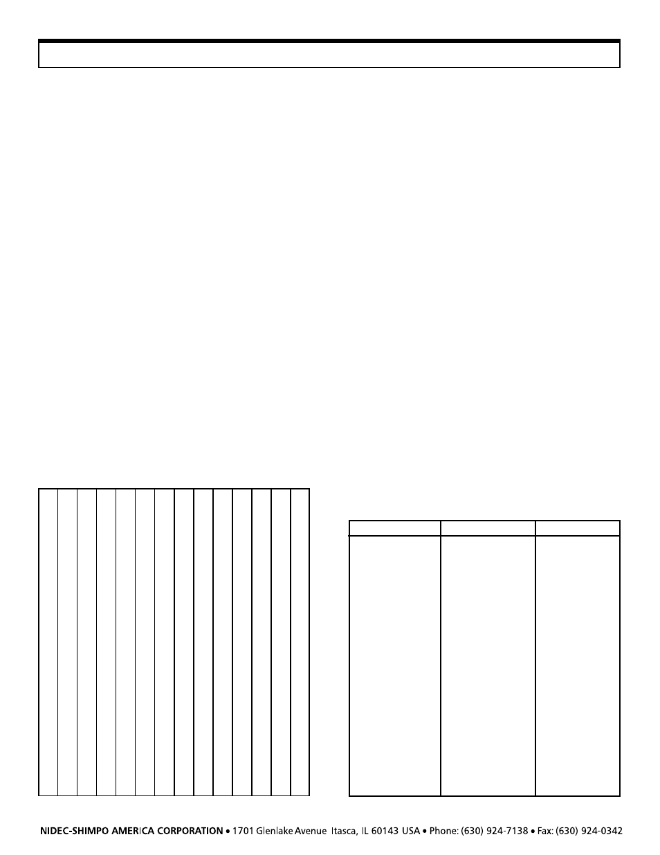
Memory Data Output
Data may be output from memory by first pressing the RECALL
button and then pressing the MEMO SET button. The main
display will briefly indicate “oUt” to confirm that the data has
been sent. The following chart indicates the order of the data
output depending upon which memory mode was used:
Output Data Format
The following chart demonstrates the format of the data as it is
output through RS232:
1
2
3
4
5
6
7
8
9 10 11 12 13 14
S T
A T
I
S T
I
C S
CR LF
CR LF
U N
I
T
S
g
f
CR LF
D A T
A
1
0
0 CR LF
M A X
—
1
0
0
0 CR LF
M
I
N
—
1
0 CR LF
P K C
0 CR LF
P K T
—
1
1
0
0 CR LF
A V G
—
9
1
2 CR LF
D E V
8
.
2 CR LF
H L M T
—
1
0
0
0 CR LF
L
L M T
—
9
0
0 CR LF
CR LF
D A T
A —
9
1
5 CR LF
1
2
L —
8
9
5 CR LF
9
9
H —
1
0
0
5 CR LF
1
0
0
9
9
0 CR LF
*
*
E N D
*
*