Pyromation Series 610 1_16 DIN User Manual
Page 54
1
/
4
-DIN,
1
/
8
-DIN &
1
/
16
- DIN Controllers & Indicators - Product Manual
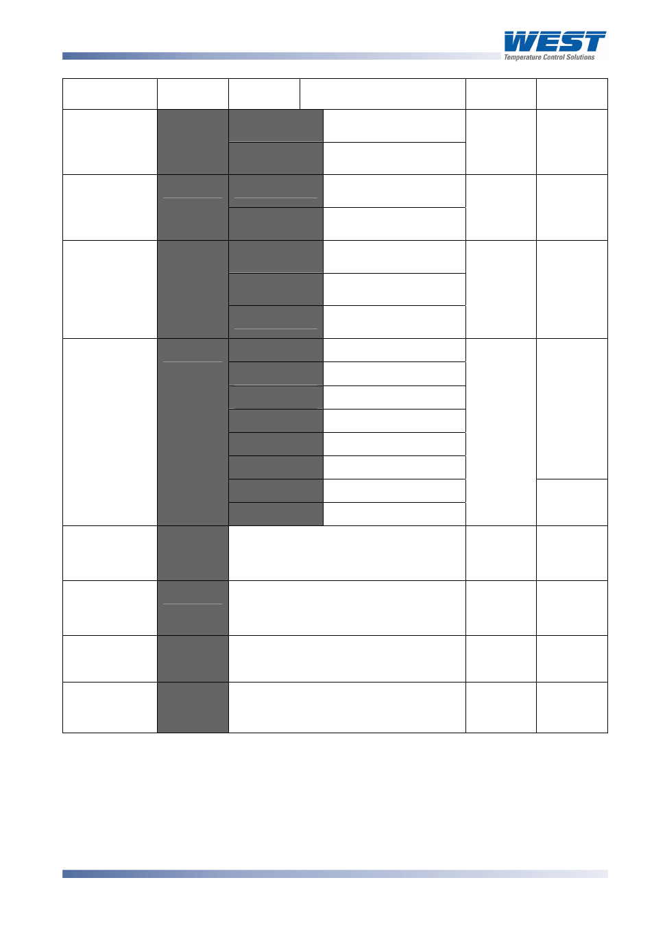
Parameter Lower
Display
Upper
Display
Description Default
Value
When
Visible
r_
o
Read only. Comms
writes ignored
3 C
r_
Ww
Read / Write. Writing via
Comms is possible
r_
Ww
Always
=-
Setpoint 1 / Setpoint 2
Select**
Digital Input 1
Usage
=#
=,
Automatic / Manual
Select**
=- @C
=
=#
=-
Setpoint 1 / Setpoint 2
Select**
=,
Automatic / Manual
Select**
Digital Input 2
Usage
=#
=+,
Remote / Local Setpoint
Select
=+- @C
=
+-)
:
0 to 20mA DC input
:
4 to 20mA DC input
:
0 to 10V DC input
:
2 to 10V DC input
:
0 to 5V DC input
:
1 to 5V DC input
@C
or
@C
=
+-)
0 to 100mV DC input
+C)
) /
Potentiometer (
≥2KΩ)
:
@C
=
+-)
+-)1
to
RSP value to be used when RSP input is
at maximum.
Range
max
@C
=
+-)
+-)'
to
RSP value to be used when RSP input is
at minimum.
Range min
@C
=
+-)
+-)
Offset applied to RSP value. Constrained
within Scale Range Upper Limit and
Scale Range Lower Limit.
@C
=
+-)
Configura-
tion Mode Lock
Code
3' N
to
Always
*Note:
Alarm parameters marked * are repeated in Setup Mode.
**Note:
If
=#
or
=#
=
=-
the remote setpoint input feature is disabled. The instrument
uses the two internal setpoints (SP1 & SP2) instead.
If
=#
and
=#
are set to the same value, the status of digital input 2 will take
precedence over digital input 1.
59305, Issue 6 – March 2006
P6100, P6120, P8100 & P4100 Model Group
Page 49