KROHNE DW 181-182-183-184 EN User Manual
Page 11
Installation and operating instructions DW 181 - 184
11
3 Commissioning
3.1 General
notes
The flow switch is delivered pre-calibrated and ready for use. Open the valves slowly when starting
operation.
3.2
Adjusting the limit switches - standard and EEx ia flow switch versions
The limit switches can be adjusted individually over the entire measuring range. To adjust, remove
the locking pin securing the cap and remove the cap.
3.2.1 Type G indicator
The limit switch adjustment is indicated by a green strip (normally closed switch) or a black strip
(normally open switch) in a graduated window. For flow switches manufactured before September 1,
1991, the strips are red (normally closed switch) or orange (normally open switch).
Each graduation corresponds to 1/10 of the total measuring range, i.e. 35 l/h for a flow range of
50…400 l/h. This system enables the limit switch to be adjusted without having to circulate fluid in
the pipe. It is only necessary to adjust the micrometer screw (item 2) in order to move the switch
support (item 3) which has the coloured strip on its upper section.
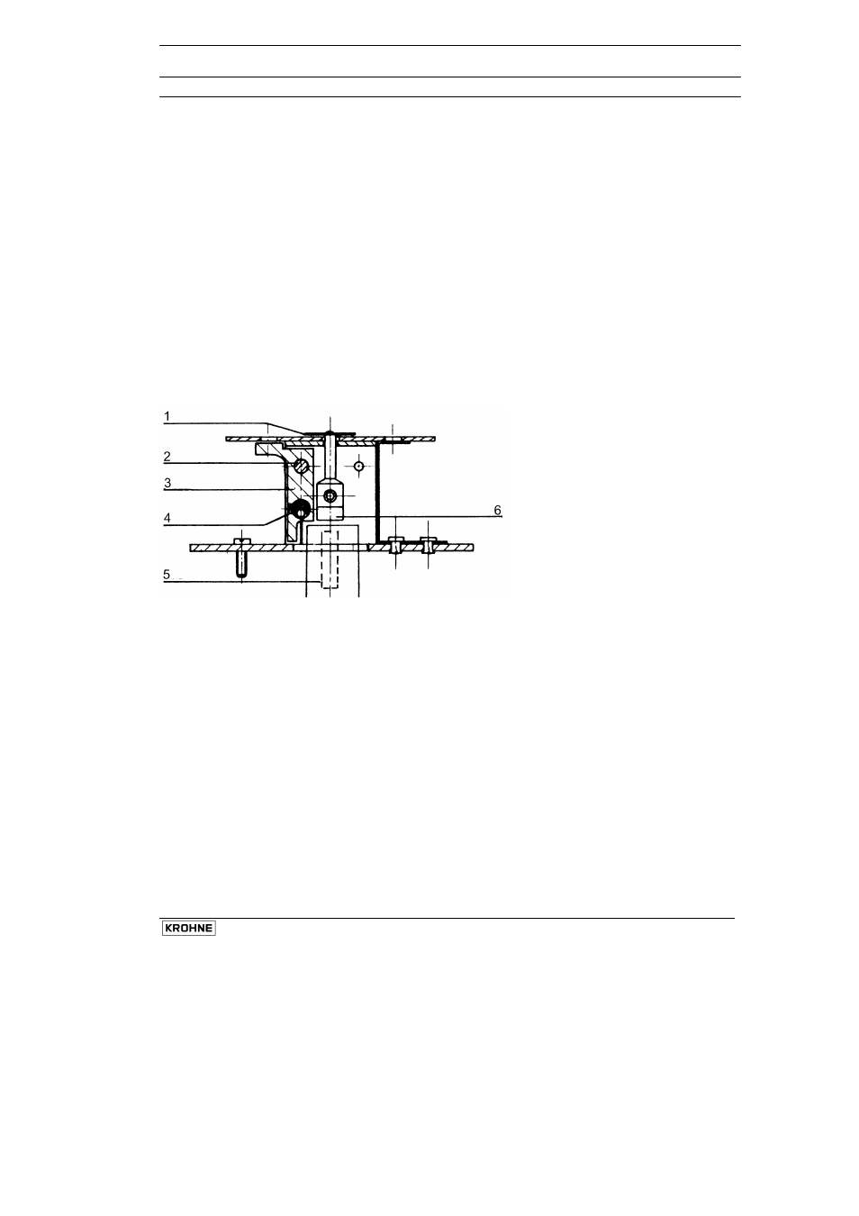
“G” linear index indicator assembly
1
Index
2 Micrometer
screw
3 Switch
support
4 Switch
5 Control
magnet
6 Following
magnet