Operation, Operation 4.1 menu mode structure – KROHNE OPTISENS ORP 8590 EN User Manual
Page 16
4
OPERATION
16
OPTISENS ORP 8590
www.krohne.com
01/2014 - 4001933801 MA OPTISENS ORP 8590 R01 en
Operation
4.1 Menu mode structure
INFORMATION!
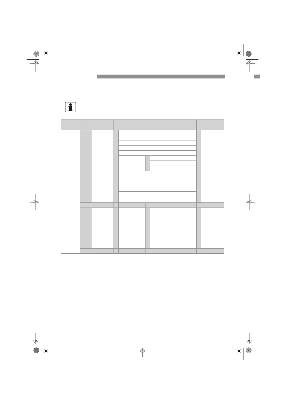
The following table just presents an overview. Additional levels are accessible from certain
menus offering the possibility to change presets.
Measuring
mode
Main menu
Submenu
Parameter
3 or 4
pages,
scrolling
with ↓ or ↑
> 2.5 s
^
A quick setup
A quick setup
A quick setup
A quick setup
>
^
A1 language
>
^
For further
information
see function
tables.
A2 Tag
A3 hold function
A4 set clock
A5 reset errors
A6 analog
outputs
>
^
A6.1 measurement
A6.3 range
A6.4 time constant
A9...A11: calibration menus for process input A;
existence of the single sub-menus depends on the
hardware setting and the used sensor (e.g. if you use a
pH sensor then only the menu A8 with the name "pH
cal." appears); refer to sensor manual for further
information.
A12...A16: calibration sub-menus for process input B,
existence also depending on the hardware setting and
the used sensor.
↓↑
↓↑
↓↑
↓↑
> 2.5 s
^
B test
B test
B test
B test
>
^
B1 Simulation
Process Input A
>
^
B1.1...B1.7: simulation menus
for process input A; existence of
the single sub-menus depends
on the hardware setting and the
used sensor, refer to sensor
manual for further information.
>
^
For further
information
see function
tables.
B2 Simulation
Process Input B
B2.1...B2.7: simulation menus
for process input B; existence of
the single sub-menus depends
on the hardware setting and the
used sensor, refer to sensor
manual for further information.
↓↑
↓↑
↓↑
↓↑
.book Page 16 Friday, January 24, 2014 11:29 AM