Installation – KROHNE OPTISENS ORP 8590 EN User Manual
Page 13
INSTALLATION
3
13
OPTISENS ORP 8590
www.krohne.com
01/2014 - 4001933801 MA OPTISENS ORP 8590 R01 en
3.5.1 Connecting the sensor cable to the signal converter
The ORP sensor is connected to the signal converter using a coax cable.
When ordering the one channel version, only the interface "Pos.A" is populated. In the version
with two channels the interfaces "Pos.A" and "Pos.B" are populated.
DANGER!
All work on the electrical connections may only be carried out with the power disconnected. Take
note of the voltage data on the nameplate!
INFORMATION!
Look at the device nameplate to ensure that the device is delivered according to your order.
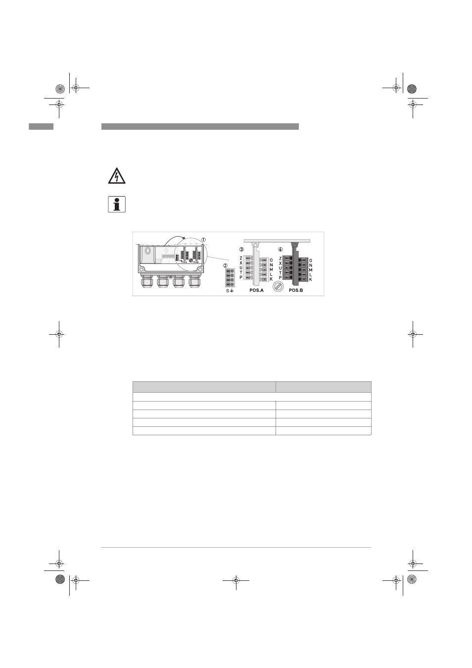
Figure 3-3: Sensor connection terminals on the signal converter dual channel version with terminal block A+B
1 Sensor connection terminals
2 Terminal block S (protective earth)
3 Terminal block A: terminals for sensor and temperature
4 Terminal block B: terminals for sensor and temperature
Wire
Wire
Wire
Wire
Terminal block Pos.A/B
Terminal block Pos.A/B
Terminal block Pos.A/B
Terminal block Pos.A/B
OPTISENS ORP 8590 with double coax cable
OPTISENS ORP 8590 with double coax cable
OPTISENS ORP 8590 with double coax cable
OPTISENS ORP 8590 with double coax cable
Inner coax shield (black)
N (ref.)
Coax core (transparent)
O (pH)
Pt100 (white)
P
Pt100 (red)
X
.book Page 13 Friday, January 24, 2014 11:29 AM