Electrical connections, 1 installation in hazardous area and bus cable, 2 foundation fieldbus electrical connection – KROHNE MFC 300 FOUNDATION FIELDBUS EN User Manual
Page 5: 3 cable types
ELECTRICAL CONNECTIONS
3
5
MFC 300
www.krohne.com
02/2013 - 4001086702 - AD MFC 300 FF R02 en
3.1 Installation in hazardous area and bus cable
We recommend that a Foundation Fieldbus network in the hazardous area should be projected in
accordance with PTB's FISCO model. The FISCO model is based on the following conditions:
• All electrical components which should be connected to the bus must be approved according
to the FISCO model (even the termination).
• The maximum cable length should not exceed 1000 m / 3280.8 ft.
• The approved input values of the field devices (U
0
, I
0
, P
0
) comply to the output values of the
power supply (e.g. segment coupler) according to: U
0
≤ U
i
; I
0
≤ I
i
; P
0
≤ P
i
.
• The values of the cable must be within the following ranges:
R' = 15…150 Ω/km; L' = 0.4…1 mH/km; C' = 45…200 nF/km
equivalent to
R' = 24…240 Ω/mile; L' = 0.65…1.6 mH/mile; C' = 72…320 nF/mile
Other limitations for the cable than the FISCO limitations are not existent. Nevertheless, a
twisted pair and shielded cable is strongly recommended.
Example: a good quality cable could have the following data: 44 Ω/km = 70.4 Ω/mile; <90 nF/km
= <144 nF/mile; attenuation at 39 kHz: <3 dB/km = <4.9 dB/mile; impedance 100 Ω at 31.25 kHz.
3.2 Foundation Fieldbus electrical connection
The output and input groups are electrically isolated from each other and from all other input
and output circuits.
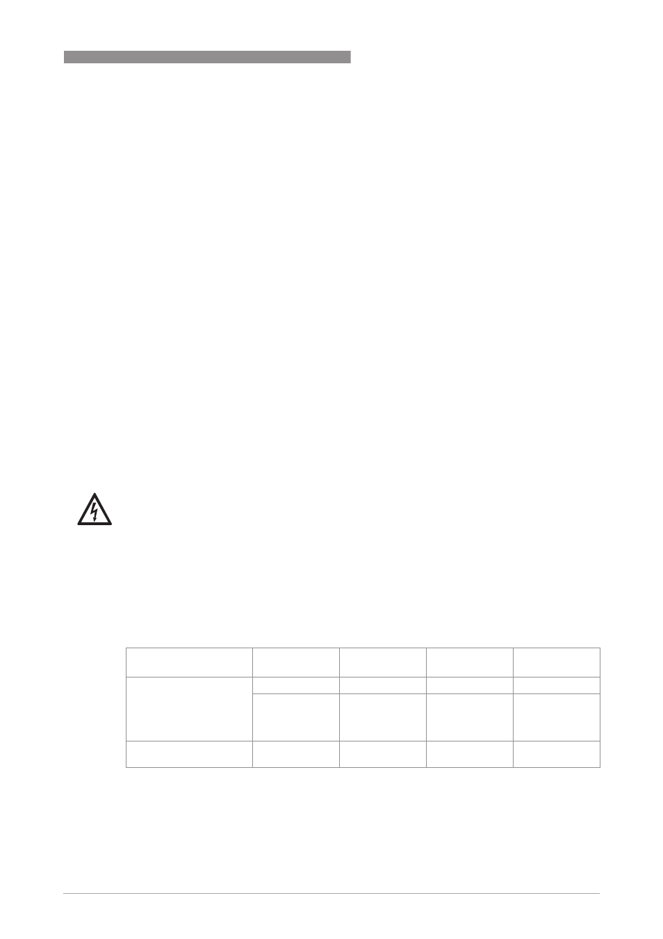
3.3 Cable types
The cable types are specified according to IEC 61158-2. Shielded cables offer the advantage of
malfunction-free operation with adequate protection against electromagnetic influences, and
make it possible to employ the full performance of the Foundation Fieldbus system.
In non-hazardous areas the maximum number of field devices is limited to 32. For detailed
information refer to the following table.
In non-hazardous areas the ignition protection class of the devices and the limited electric power
available limit the number of field devices to 4.
DANGER!
The signal converter must be properly grounded to avoid personnel shock hazard. All directions,
operating data and connection diagrams do not apply to devices used in hazardous areas; in such
cases, read the special Ex instructions without fail!
Core cross-section
0.8 mm
2
or
AWG 18
0.32 mm
2
or
AWG 22
0.13 mm
2
or
AWG 26
1.25 mm
2
or
AWG 16
Cable type
A
A
A
A
B
B
B
B
C
C
C
C
D
D
D
D
twisted pair,
individually
shielded
individual or
multiple twisted
pairs with overall
shield
multiple twisted
pairs, without
shielding
multiple non-
twisted cables,
without shielding
Max. length
incl. branch line
1900 m / 6200 ft
1200 m / 3900 ft
400 m / 1300 ft
200 m / 650 ft