Operation – KROHNE MFC 300 FOUNDATION FIELDBUS EN User Manual
Page 25
OPERATION
4
25
MFC 300
www.krohne.com
02/2013 - 4001086702 - AD MFC 300 FF R02 en
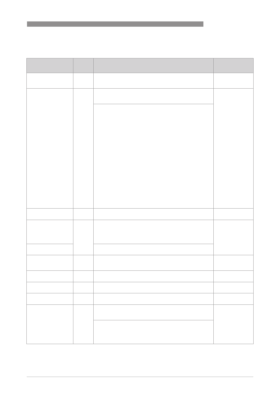
4.5.2 Manufacturer specific parameters of the signal converter for Transducer Block
Parameter
Parameter
Parameter
Parameter
Subelement
Access
Description and settings
Initial Value
COLLECTION_
COLLECTION_
COLLECTION_
COLLECTION_
DIRECTORY
DIRECTORY
DIRECTORY
DIRECTORY
Collection Directory
Collection Directory
Collection Directory
Collection Directory
R
A directory that specifies the number, starting indices and DD
Item IDs of the data collections in each transducer within a
Transducer Block.
-
PRIMARY_VALUE
PRIMARY_VALUE
PRIMARY_VALUE
PRIMARY_VALUE
PRIMARY_VALUE_
PRIMARY_VALUE_
PRIMARY_VALUE_
PRIMARY_VALUE_
RANGE
RANGE
RANGE
RANGE
R/W
There are 19 Primary Values (1…19); Setting is for all
identical. Therefore the description follows only for Primary
Value 1.
-
Setting:
•
1 (Mass Flow in kg/s)
•
2 (Density in kg/m
3
)
•
3 (Tube Temp. in °C)
•
4 (Flow Velocity in m/s)
•
5 (Volume Flow in m
3
/s)
•
6 (Conc. Mass Flow 1 in kg/s)
•
7 (Conc. Mass Flow 2 in kg/s)
•
8 (Conc. Volume Flow 1 in m
3
/s)
•
9 (Conc. Volume Flow 2 in m
3
/s)
•
10 (Concentration 1 in %sol/wt)
•
11 (Concentration 2 in %sol/wt)
•
12 (2 Phase Signal in %)
•
13 (Sensor Average in %)
•
14 (Sensor Deviation in %)
•
15 (Drive Level in %)
•
16 (Tube Frequency in Hz)
•
17 (Strain MT in Ohm)
•
18 (Strain IC in Ohm)
•
19 (Electronic Temp. in °C)
PRIMARY_VALUE_1
PRIMARY_VALUE_1
PRIMARY_VALUE_1
PRIMARY_VALUE_1
Primary Value 1
Primary Value 1
Primary Value 1
Primary Value 1
R
The measured value and status available to the Function
Block.
-
STATUS
Status
R
Digital transducers, unlike their analogue versions, can detect
faults that make the measurement bad or prevent the
actuator from responding. This additional, valuable
information will be passed along with each transmission of a
data value in the form of a status attribute.
-
VALUE
Value
A numerical quantity entered by a user or calculated by the
algorithm.
PRIMARY_VALUE_1_
PRIMARY_VALUE_1_
PRIMARY_VALUE_1_
PRIMARY_VALUE_1_
RANGE
RANGE
RANGE
RANGE
Primary Value 1 Range
Primary Value 1 Range
Primary Value 1 Range
Primary Value 1 Range
R
The high and low range limit values, the engineering units
code and the number of digits to the right of the decimal point
to be used to display the Primary Value.
-
EU_100
Engineering Unit 100
R
The engineering unit value which represents the upper end of
range of the associated Block Parameter.
-
EU_0
Engineering Unit 0
R
The engineering unit value which represents the lower end of
range of the associated Block Parameter.
-
UNITS_INDEX
Inits Index
R
Device Description units code index for the engineering unit
descriptor for the associated block value.
-
DECIMAL
Decimal (Point)
R
The number of digits to the right of the decimal point which
should be used by an interface device in displaying the
specified parameter.
0
Setting:
0...255