Operation – KROHNE MFC 300 FOUNDATION FIELDBUS EN User Manual
Page 20
4
OPERATION
20
MFC 300
www.krohne.com
02/2013 - 4001086702 - AD MFC 300 FF R02 en
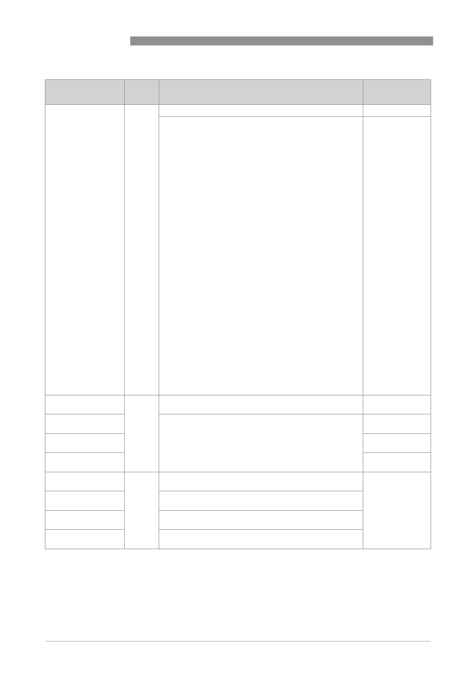
DIAGNOSIS_DEV
DIAGNOSIS_DEV
DIAGNOSIS_DEV
DIAGNOSIS_DEV
Diagnosis Device
Diagnosis Device
Diagnosis Device
Diagnosis Device
R
Display of maximum 8 (error) messages.
Current diagnosis
Setting:
0:Startup phase / 255:no message
F:
F:
F:
F: Device Error / Configuration / Parameter / Software User
Interface / Hardware Detection / Hardware Settings / Display /
RAM/ROM Error IO1 / IO 1 / RAM/ROM Error IO2 / IO 2 /
Fieldbus / Current Output C / Current Output B / Current
Output A / Sensor Electronics / SE Drive Failure / SE Data
Error / Sensor: Local Data Error / Sensor: Global Data Error /
SE Hardware Failure / SE Data Different / SE Defective /
Interface PCB Failure / SE Wiring Error / 2 Phase Flow /
RS485/Modbus / Application Error / Backup 2 Settings /
Backup 1 Settings / Factory Settings / Active Settings / Over
Range C / Wiring B / Wiring A / Over Range B (current) / Over
Range A (current) / Over Range A (pulse) / Over Range B
(pulse) / Over Range D / Open Circuit C / Open Circuit B / Open
Circuit A / Sensor Exceeding Limit / Sensor Exceeding Limit /
Sensor Electronics / Tube Not Oscillating / System Control /
Stop Mode / Sensor: System Error / SE Comms. Failure
S:
S:
S:
S: Out Of Specification / Backplane Invalid / Overflow Totaliser
1 / Overflow Totaliser 3 / Overflow Totaliser / Overflow
Totaliser 2 / Density Calib. Failed / Sensor Signal Error /
Excessive Noise / External Vibration / Sensor Levels /
Temperature Drift / Tube Asymmetry / System Control / SE
PCB Temperature / Tube Temperature / Density / Startup /
Power Fail / BE PCB Temperature / Res. Circ. Defective / SE
Defective / 2 Phase Flow / Interface PCB Fault / Checks In
Progress
C:
C:
C:
C: Sensor Electronics / Standby Mode / Zero Calibration
I:
I:I:
I: Optical Interface / Backplane Difference / Backplane
Settings / Backplane Sensor / Over Range Display 1 / Over
Range Display 2 / Control Input A act. / Control Input B act. /
Power Fail / Totaliser 1 Stopped / Totaliser 3 Stopped /
Totaliser 1 Stopped / Totaliser 2 Stopped / Baudrate Search /
No Data Exchange / Write Cycles Overfl.
Current diagnosis
DISPLAY_CNFG
DISPLAY_CNFG
DISPLAY_CNFG
DISPLAY_CNFG
Display Configuration
Display Configuration
Display Configuration
Display Configuration
R/W
Select the function block output value to display at which line.
For details see subelements.
-
DISP_LINE1
Display Line 1
Setting:
AI1 / AI2 / AI3 / AI4 / AI5 / AI6 / PID / INT1 / INT2 / INT3
AI1
DISP_LINE2
Display Line 2
AI2
DISP_LINE3
Display Line 3
AI3
ELECTRONIC_INFO
ELECTRONIC_INFO
ELECTRONIC_INFO
ELECTRONIC_INFO
Electronic Information
Electronic Information
Electronic Information
Electronic Information
R
Information about ident number, electronic revision and
production date. For details see subelements.
-
IDENT_NUMBER
Ident Number
Actual ident number
ELECTRONIC_REV
Electronic Revision
Actual electronic revision
PRODUCTION_DATE
Production Date
Date of production
Parameter
Parameter
Parameter
Parameter
Subelement
Access
Description and settings
Initial Value