1 voltage adjustment, Function of controls, indicators and terminals – KEPCO RKW 300W Series Operator Manual User Manual
Page 8
6
RKW 300W 060110
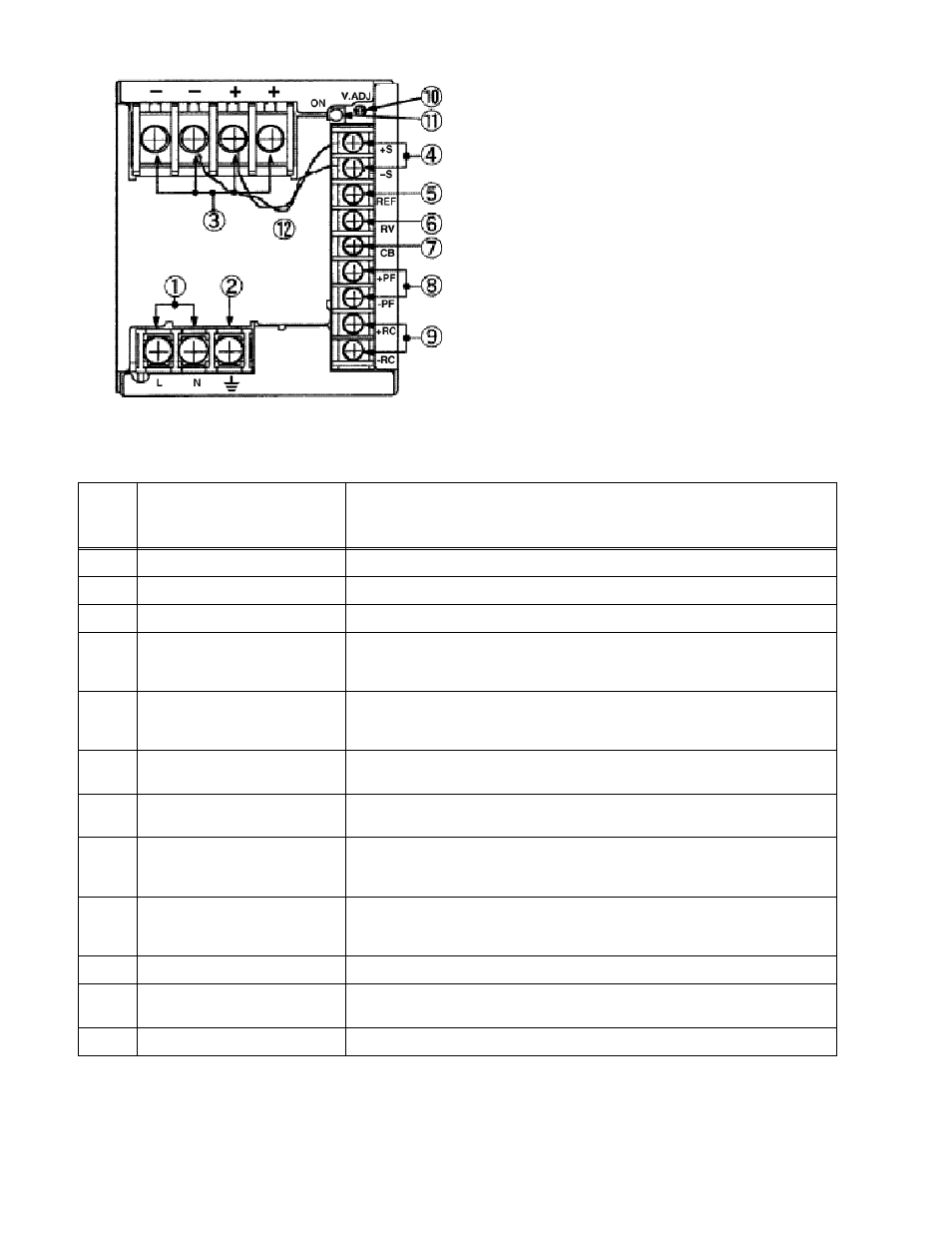
FIGURE 4. LOCATIONS OF OPERATING CONTROLS, INDICATORS AND TERMINALS
3.1
VOLTAGE ADJUSTMENT
Output voltage can be manually adjusted with the voltage adjustment control, Vadj (see Figure 4).
To adjust voltage, first place the unit under an operating load, then monitor the (+)S and (–)S
TABLE 3. FUNCTION OF CONTROLS, INDICATORS AND TERMINALS
FIG. 4
INDEX
NO.
CONTROL, INDICATOR,
TERMINAL
FUNCTION
1
A-C Input (L, N)
Connect to AC: 100 to 240V input line.
2
Frame Ground (earth)
Connect to earth ground. This terminal is connected to the case.
3
DC Output (+, –)
Connect to load (see Figure 8).
4
Sense (+S, –S)
Used to compensate for voltage drop in the connecting lines from the output terminal
to a load; they are connected to ± DC Output terminals for local sensing (see Figure
8).
5
Output Voltage Reference (REF)
Using REF terminal (together with the RV terminal) allows all the output voltages of
slave power supplies to be controlled by one voltage adjustment of a master power
supply (normally connected to the RV terminal with a metal shorting link).
6
Remote Voltage Adjust (RV)
This terminal (together with the REF terminal) is used for remotely controlling output
voltage (see PAR. 3.2).
7
Current Balance (CB)
This terminal is used when several power supplies are connected in parallel (see PAR.
5.3).
8
Power Failure (+PF, -PF)
These terminals output an open logic signal if output voltage drops to 80 % or lower of
a set voltage, or if output voltage is shut down due to overvoltage or overcurrent pro-
tection, fan speed failure, or overheating. (see Figures 6 and 7 ).
9
Remote ON-OFF (+RC, –RC)
Output is turned ON-OFF by shorting-opening the RC terminals (output OFF when
open). RC terminals are isolated from input and output terminals. Normally, ±RC ter-
minals are shorted with a metal shorting link (see PAR. 3.3).
10
Output Voltage Trim Adjust (Vadj)
Adjusts output voltage.
11
Output Voltage On indicator
(green)
Green LED lights when output voltage is present.
12
Local Sensing Cable Kit
Connects ± DC Output to ±S for local sensing (see Figure 8).
NOTE Unit is shipped with shorting links (not
shown) connecting +RC to –RC (see PAR. 3.3)
and REF to RV (see PAR. 3.2) and with local
sensing cables installed (connects +DC Output to
+S and –DC Output to –S) (see PAR. 5.2)