Introduction, 1 scope of manual, 2 description – KEPCO RKW 300W Series Operator Manual User Manual
Page 3: Specifications, Table 1. output ratings and specifications
RKW 300W 060110
1
1.
INTRODUCTION
1.1
SCOPE OF MANUAL
This Operator's Manual covers the installation and operation of the Kepco RKW 300W Series of
PFC (Power Factor Corrected), RoHS (Reduction of Hazardous Substances) compliant, switching
power supplies. For service information, write directly to: Kepco Inc., 131-38 Sanford Avenue,
Flushing, New York, 11355, U.S.A. Please state Model Designation and Serial Number of your
RKW Power Supply. This information can be found on the nameplate of the unit.
1.2
DESCRIPTION
The Kepco RKW 300W Series consists of seven models of switching power supplies, each with a
single output as shown in Table 1. Units may be operated with a nominal 100V a-c to 240V a-c
(input voltage range 85 to 265 Va-c), 50-60 Hz (input frequency range 47-66Hz). They will also
operate on 110V to 370V d-c input. The RKW 300W Series employs a light weight ferrite core with
200 KHz switching frequency. Regulation is provided by pulse width modulation. A power stage
with a MOSFET on each side of the primary winding, operating in the forward mode provides a
smooth isolated d-c output. A thyristor circuit prevents excessive turn-on current surge. Overvolt-
age, overtemperature, fan failure and power failure protections and an isolated remote TTL ON-
OFF control are provided. An LED “output voltage ON” light and an output voltage adjust trimmer
are visible near the output terminals (upper right side of the front panel). Units are manufactured
on a steel frame with a steel cover.
2.
SPECIFICATIONS
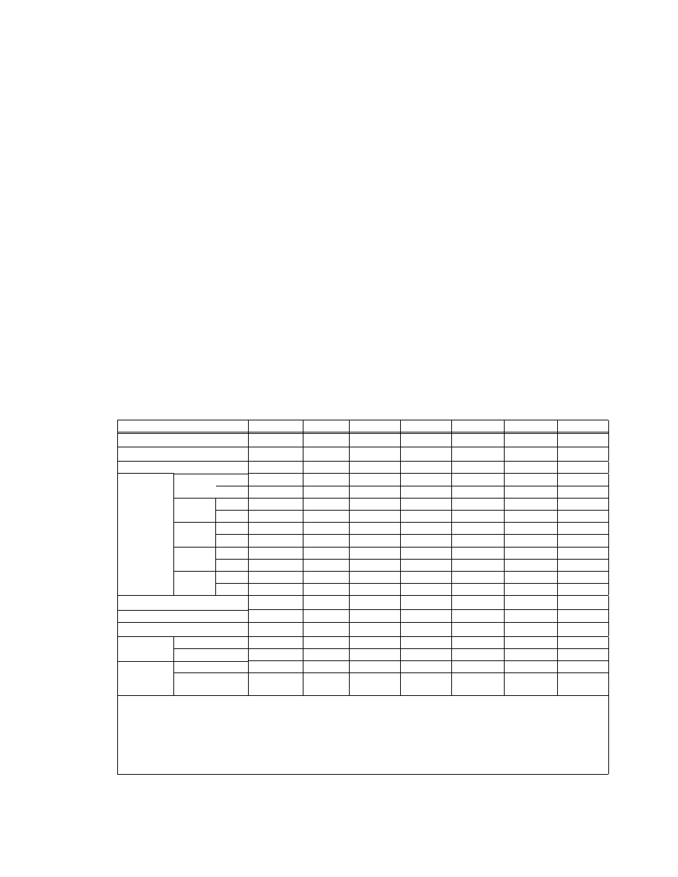
Table 1 contains specifications and operating limits of individual RKW 300W Series models. Table
2 contains specifications and operating limits common to all RKW 300W Series Models. These
specifications are at nominal input voltages at 25°C unless otherwise specified.
TABLE 1. OUTPUT RATINGS AND SPECIFICATIONS
MODEL RKW 300W
3.3-70K
5-60K
12-27K
15-22K
24-14K
28-12K
48-7K
Output Volts d-c
3.3V
5V
12V
15V
24V
28V 48V
Adjustment Range
1.8-3.6
3.5-6.0
7.2-14.4
10.5-18.0
16.8-28.8
19.6-33.6
33.6-52.8
Voltage Setting
3.3 ±0.03
5 ±0.05
12 ±0.12
15 ±0.15
24 ±0.24
28 ±0.28
48 ±0.48
–10°C
to 40°C
Amps
70
60
27
22
14
12
7
Watts
231
300
324
330
336
336
336
Maximum
Output
Ratings
(A,W)
50°C
amb
Amps
61.6
60
27
22
14
12
7
Watts
203.3
300
324
330
336
336
336
56°C
amb
Amps
56
52.8
23.8
19.4
12.3
10.6
6.2
Watts
184.8
264
285.1
290.4
295.7
295.7
295.7
60°C,
amb
Amps
52.6
48
21.6
17.6
11.2
9.6
5.6
Watts
173.7
240
259.2
264
268.8
268.8
268.8
65°C,
amb
Amps
49
42
18.9
15.4
9.8
8.4
4.9
Watts
161.7
210
226.8
231
235.2
235.2
235.2
Overcurrent Setting (Amps)
(1)
73.5 - 91
63 - 78
28.4 - 35.1 23.1 - 28.6 14.7 - 18.2
12.6 - 15.6
7.4 - 9.1
Current Short Circuit
90
82
35
29
20
17
11
OVP Setting (Volts)
(2)
4.0 - 4.6
6.2 - 7.0
14.8 - 16.8 18.6 - 21.0 29.8 - 33.6
34.7 - 39.2 55.0 - 59.9
Efficiency
% typical
AC Input 100V
68
74
76
77
80
80
81
AC Input 200V
72
78
80
81
84
84
85
Ripple &
Noise
(3)
(mV, p-p)
ripple 80
80
120
120
150
150
200
ripple noise
120
120
150
150
200
200
300
(1)
Square type. If overcurrent condition continues beyond 30 seconds, the output is shut OFF. Recovery is by removing
power and reapplying power after about 40 seconds or by opening and reclosing the RC terminals .
(2)
When overvoltage is detected, output is shut OFF. Recovery is by removing power and reapplying power after about
40 seconds or by opening and reclosing the RC terminals (no delay).
(3)
Ripple and noise specifications are 1.5 times indicated values for temperature range of -10 to 0°C. Ripple and noise
levels above are satisfied when conditions are 0 to 100% load, 0 to 65°C (derated from 50 to 65°C per Figure 2, der-
ated from 40 to 65°C for 3.3V model), and bandwidth
≤ 100MHz.