Figure 7. rkw 300w power failure timing diagram, 5 undervoltage, Load connection – KEPCO RKW 300W Series Operator Manual User Manual
Page 11: 1 connecting the load using local sensing, 2 connecting the load using remote sensing, 3 parallel connection, Rkw 300w power failure timing diagram, R. 5.2)
RKW 300W 060110
9
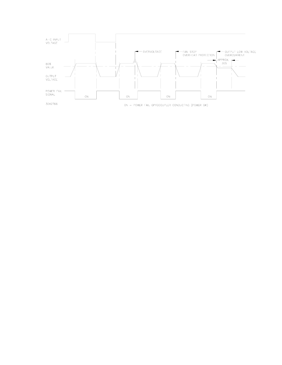
FIGURE 7. RKW 300W POWER FAILURE TIMING DIAGRAM
4.5
UNDERVOLTAGE
If the output voltage of the power supply falls below 80 percent of the programmed voltage the
power failure alarm will go to the high logic state.
5.
LOAD CONNECTION
5.1
CONNECTING THE LOAD USING LOCAL SENSING
To connect the load for local sensing, connect the +S to (+) terminal and –S to (–) terminal. The
load is connected across DC output (+) and (–) terminals (see Figure 8). For the RKW 3.3-70K
and RKW 5-60K use the two high and the two low output terminals.
5.2
CONNECTING THE LOAD USING REMOTE SENSING
For remote sensing the load is connected as shown in Figure 8. Remote error sensing at the load
terminals compensates for a voltage drop in the connecting wires as indicated in Table 2. For
remote sensing, the sensing cables must be removed from the +S to (+) and –S to (–-) terminals.
NOTE: If oscillations set off the overvoltage protection, install one external electrolytic capacitor,
rated 470µF min. between the (+) and +S terminals and one between the (–) and –S terminals.
5.3
PARALLEL CONNECTION
RKW 300W Power Supplies can be connected in parallel (with or without N+1 redundancy). Use
twisted or shielded wire for connection to RV and –S terminals. The impedance of the load wires
between each power supply and load should be the same.
For a single remote ON-OFF signal to turn off all parallel-connected units, connect together all
+RC terminals and connect together all –RC terminals. Figure 9 illustrates connection of up to four
(maximum) power supplies in parallel. Output current for a parallel connection operating into a
single load is equalized by connecting the CB terminals as shown. Output current for a parallel
connection operating into a single load is equalized by connecting the CB terminals as shown.
Refer to PAR. 5.3.1 for conditions required for proper current equalization (balancing).
N+1 Redundancy. An N+1 system requires one additional power supply than necessary to supply
the load. If one of the parallel-connected units fail, the others will continue to provide power to the
load without down time. For redundancy, add isolation diodes as shown in Figure 9.