Alarm functions, 1 overvoltage and overtemperature protection, 2 overcurrent protection – KEPCO RKW 300W Series Operator Manual User Manual
Page 10: 3 fan failure, 4 optical coupler output alarm circuit, Figure 6. output alarm circuit, optically isolated, Output alarm circuit, optically isolated, See figures 6 and
8
RKW 300W 060110
terminals are shorted, the output returns to within specifications. At low level logic, the maximum
source current is 1.6mA and at high level the sink current is 1.0mA. The RC terminals must
remain shorted if remote ON-OFF is not used. The RC terminals are isolated from both the AC
input and DC output terminals.
4.
ALARM FUNCTIONS
4.1
OVERVOLTAGE AND OVERTEMPERATURE PROTECTION
When the output voltage of the RKW 300W Power Supply increases beyond the specified values
(see Table 1), the output is cut OFF and the fan turns OFF. To restart (reset) the unit, remove AC
input power, wait about 40 seconds, then reconnect AC input power; or open and then reclose the
RC terminals.
When the internal temperature of the RKW 300W Power Supply increases beyond the specified
values (see Table 1), the output is cut OFF and the fans turn OFF. The restart cycle (Power ON)
should not begin until the temperature returns to within specifications. To restart (reset) the unit,
remove AC input power, wait about 40 seconds, then reconnect AC input power.
The alarm circuit is a diode transistor optical coupler. The transistor is normally conducting. When
the alarm activates, the transistor cuts off and the collector emitter circuit opens (see PAR. 4.4).
4.2
OVERCURRENT PROTECTION
The output characteristic of the power supply is a square type, and the unit is set to shut down if out-
put current exceeds specifications (see Table 1) for more than 30 seconds. To restart (reset) the
unit, remove AC input power, wait about 40 seconds, then reconnect AC input power. or open then
reclose the RC terminals (see PAR. 3.3).
4.3
FAN FAILURE
A cut off of the rotation supply voltage causes the output to shut down and the fan to turn OFF. Fan
failure and all the other protection circuit operations are indicated by an open circuit across the (±)
PF terminals. To restart (reset) the unit remove the AC input power, wait about 40 seconds, then
reconnect AC input power; or open then reclose the RC terminals. If fan rotation is out of specifi-
cation the power supply will not recover
4.4
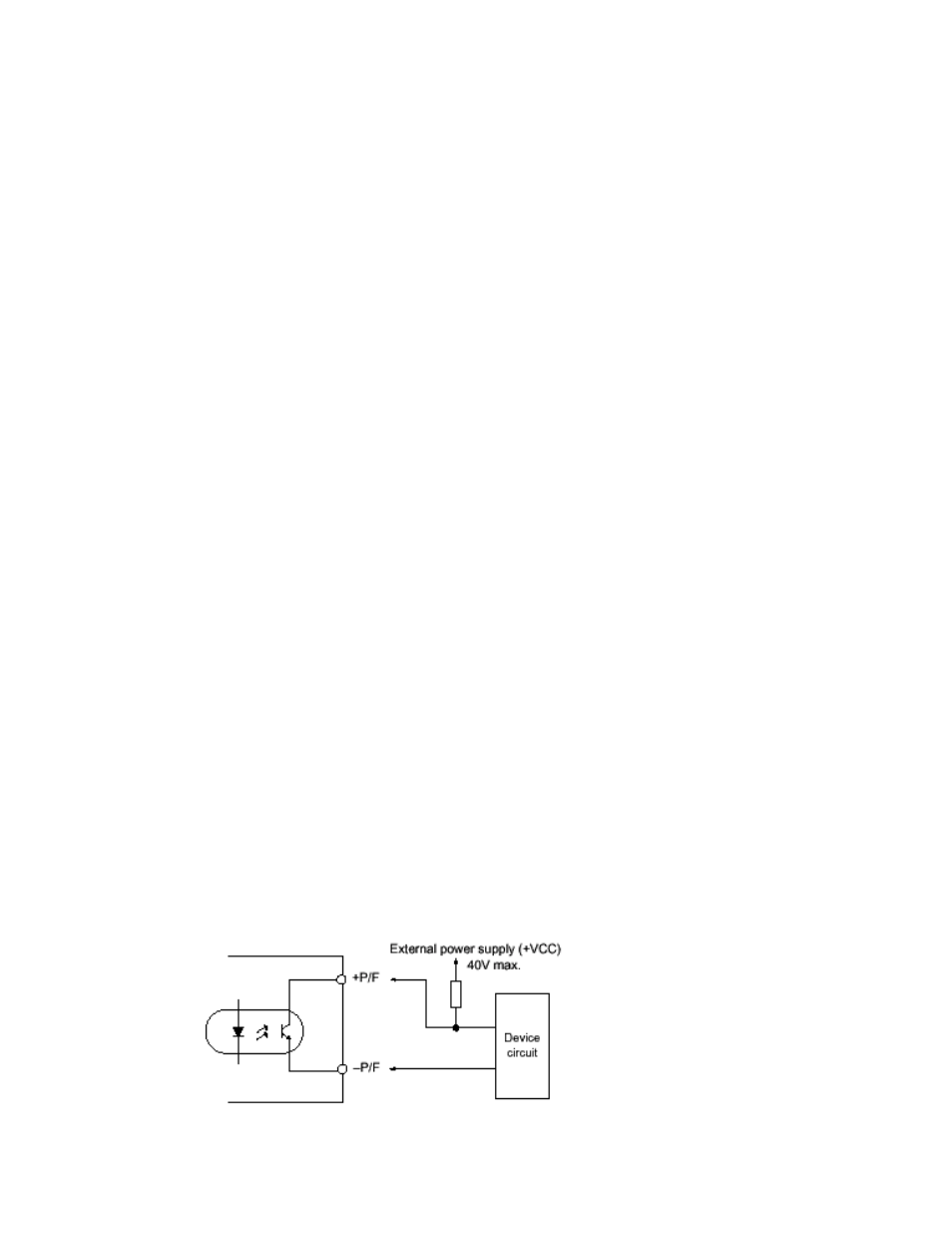
OPTICAL COUPLER OUTPUT ALARM CIRCUIT
When the output voltage falls to less than about 80 percent of programmed output voltage the
alarm is activated: a high logic level appears at the ±PF terminals (see Figure 6). The default state
of the alarm is logic low. The sink current is 50mA maximum, the maximum collector to emitter
saturation voltage is 0.40 Volts, and the collector to emitter voltage is 40 volts maximum. The PF
terminals are isolated from the AC input and DC output terminals. Insulation resistance between
the PF terminals and the AC input terminals is the same as the insulation resistance between the
input and output. Insulation resistance between the PF terminals and the output terminals is the
same as the insulation resistance between the output and ground.
FIGURE 6. OUTPUT ALARM CIRCUIT, OPTICALLY ISOLATED