Local sensing (factory default), Remote sensing select, Analog i/o connections – KEPCO BOP-GL 1KW Quick Start Guide User Manual
Page 6: Trigger connections, Gpib connections, Rs 232 connections
6
228-1699 REV 2
093013
KEPCO, INC. 131-38 SANFORD AVENUE FLUSHING, NY. 11355 U.S.A. TEL (718) 461-7000 FAX (718) 767-1102
http://www.kepcopower.com email: [email protected]
MON and COM MON to monitor voltage at the BOP-
GL output.
LOCAL SENSING (FACTORY DEFAULT).
Unit is shipped with local sensing links installed:
OUT S connected to OUT MON and COM MON
connected to COM S (see Figure 4A).
REMOTE SENSING SELECT. First remove the
factory-installed local sensing links between OUT S
and OUT MON and between COM MON and COM
S. Then connect the OUT S and COM S lines at the
load (see Figure 4B) using #22 AWG wire, twisted
pair.
ANALOG I/O CONNECTIONS. The Analog I/O
Port connector, located on the rear panel of the
BOP-GL 1KW power supply (see Figure 3), provides
access to analog programming inputs which can
control the mode of operation (voltage or current),
output voltage or current, and establish positive and
negative voltage and current limits. Output analogs
corresponding to output current and voltage are also
provided. Refer to Operator’s manual for details.
TRIGGER CONNECTIONS. The Trigger Port
(see Figure 3) provides for an external trigger input
for use with SCPI *TRG and TRIG commands. Refer
to Operator’s manual for details.
GPIB CONNECTIONS. Your computer must
have a GPIB interface card installed. Connect the
power supply to the computer’s GPIB interface card.
Use a standard GPIB interface cable at the GPIB
port on the rear panel (see Figure 3). The default
GPIB address is 6; refer to the Operator’s Manual to
change it.
RS 232 CONNECTIONS. Connect the BOP-GL
to a modem using a Null Modem patch cable at the
RS 232 port located on the rear panel (See Figure
3). A Null Modem cable is not required for older
MAC computers with D-sub serial port in which the
RXD and TXD line transposition is accomplished via
external hardware. The baud rate (9600 or 19200) is
established by performing a “Reset Power-up” on
page 8.
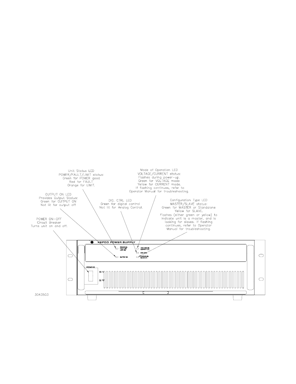
FIGURE 2. BOP-GL 1KW SERIES, FRONT PANEL CONTROLS AND INDICATORS