I — description, Table 1. bop-gl 1000 watt model parameters, Ii — unpacking – KEPCO BOP-GL 1KW Quick Start Guide User Manual
Page 2: Iii — equipment supplied, Table 2. equipment supplied, Description, Unpacking, Equipment supplied, See ta ble 2
2
228-1699 REV 2
093013
KEPCO, INC. 131-38 SANFORD AVENUE FLUSHING, NY. 11355 U.S.A. TEL (718) 461-7000 FAX (718) 767-1102
http://www.kepcopower.com email: [email protected]
I — DESCRIPTION
The BOP 1KW-GL Series hereafter referred to as
BOP-GL, are true 4-quadrant programmable voltage
and current power supplies, meaning they are capa-
ble of both sourcing and sinking power (see Figure
1).
The BOP-GL models have been optimized for
exceptionally low current ripple and noise and
improved stability (drift and temperature), making
them ideal for driving inductive loads such as large
magnets or motors. These bipolar power supplies
pass smoothly through zero without switching to pro-
vide true ± voltage and ± current. These BOP-GL
power supplies use switch mode technology for low
dissipation. A bi-directional, isolating, a-c input
power factor correcting (PFC) circuit recuperates
energy sinked from an active load and sends it back
into the line to maintain low dissipation.
These BOP power supplies can be controlled
remotely by an analog ±10V input for the main chan-
nel (voltage or current), and by a +1 to +10V input
for the limit channels. They can also be controlled
through one of the standard digital interfaces (GPIB
or RS 232) to set voltage and current and the four
protection limits (+voltage, –voltage, +current and –
current.) Output voltage and current can be remotely
monitored via the analog monitor signals present at
the rear panel Analog I/O Port connector, or by using
SCPI commands via either the RS 232 or GPIB
ports.
.
II — UNPACKING
This instrument has been thoroughly inspected and
tested prior to packing and is ready for operation.
After careful unpacking, inspect for shipping damage
before attempting to operate. Perform the “Prelimi-
nary Operational Check” on page 5. If any indication
of damage is found, file an immediate claim with the
responsible transport service.
III — EQUIPMENT SUPPLIED
See Table 2.
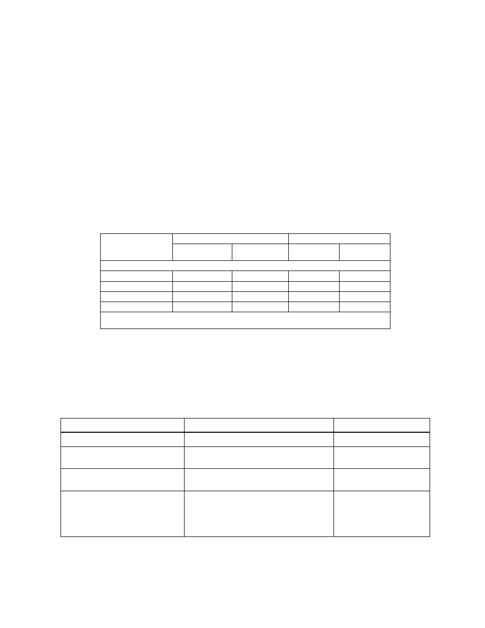
TABLE 1. BOP-GL 1000 WATT MODEL PARAMETERS
Model
d-c Output Range
Closed Loop Gain
E
O Max
I
O Max
Voltage
Channel
Current
Channel
1000 WATT MODELS
BOP 10-100GL
±10V d-c
±100A d-c
1.0
10.0
BOP 20-50GL
±20V d-c
±50A d-c
2.0
5.0
BOP 36-28GL
±36V d-c
±28A d-c
3.6
2.8
BOP 50-20GL
±50V d-c
±20A d-c
5.0
2.0
NOTE: When connecting active loads, the steady-state voltage of the active load must not exceed the maximum
voltage rating of the BOP. Otherwise the overvoltage protection will shut down the power supply.
TABLE 2. EQUIPMENT SUPPLIED
ITEM
FUNCTION
PART NUMBER
Source Power Entry mating connector
Mates with source power entry connector
142-0381 (Kepco) (IEC 320)
PAR/SER CONTROL - IN
mating connector
Mates with PAR/SER CONTROL - IN port to allow
access to pins required for calibration
142-0488 (Kepco)
Mating Connector, Trigger
Mates with Trigger port.
142-0527 (Kepco)
SP2501 (CUI Stack)
Mating Connector, Analog I/O Port
(15-pin DSUB Connector)
Mates with connector for Analog I/O port A2A5J6
Dsub 15 pin hood
Dsub 15 pin male
108-0374
(Tyco-Amp 207470-1)
142-0449
(Amphenol 17S-DA15P)