Turning off the modem, Maintenance, Software appendix – In-Situ TROLL Link 100 Quick Start Guide User Manual
Page 3
Information subject to change without notice. In-Situ, In-Situ logo, BaroMerge, BaroTROLL, HERMIT, iSitu, Pocket-Situ, RDO, RuggedCable, RuggedReader, TROLL, and Win-Situ are trademarks or registered trademarks of In-Situ Inc.
©
2013. All rights reserved.
6. Connect the white lead (positive) from the solar panel to
the screw terminal labeled "SOLAR+". Tighten the
screw terminal.
7. Tighten the dome connector cap to ensure that the port
with the cable is watertight.
Connecting the TROLL LINK to the External Battery
Kit Enclosure
1. Remove two dome connector caps, one from the outside
of the battery kit enclosure, and one from the TROLL
Link Telemetry System. Remove the port plugs. Save
the plugs for later use.
2. Insert the separate power cable shipped with the
external battery kit into one dome connector cap, and
then through the battery kit enclosure.
3. Connect the black lead (negative) of the cable to the
"BATT-" screw terminal of the battery box.
4. Connect the white lead (positive) of the cable to the
"BATT+" screw terminal of the battery box.
5. Insert the other side of the cable through the remaining
dome connector cap. There should be two dome
connector caps on the cable, oriented in opposite
directions.
6. Insert the cable through the dome connector to the inside
of the enclosure.
7. Connect the black lead (negative) of the external battery
kit cable to the "SOLAR-" screw terminal of the
enclosure.
8. Connect the white lead (positive) of the external battery
kit cable to the "SOLAR+" screw terminal of the
enclosure.
9. Tighten all dome connector caps so the ports with cable
are watertight.
Installing a Battery
1. Install batteries with the terminals oriented toward the
top of the enclosure.
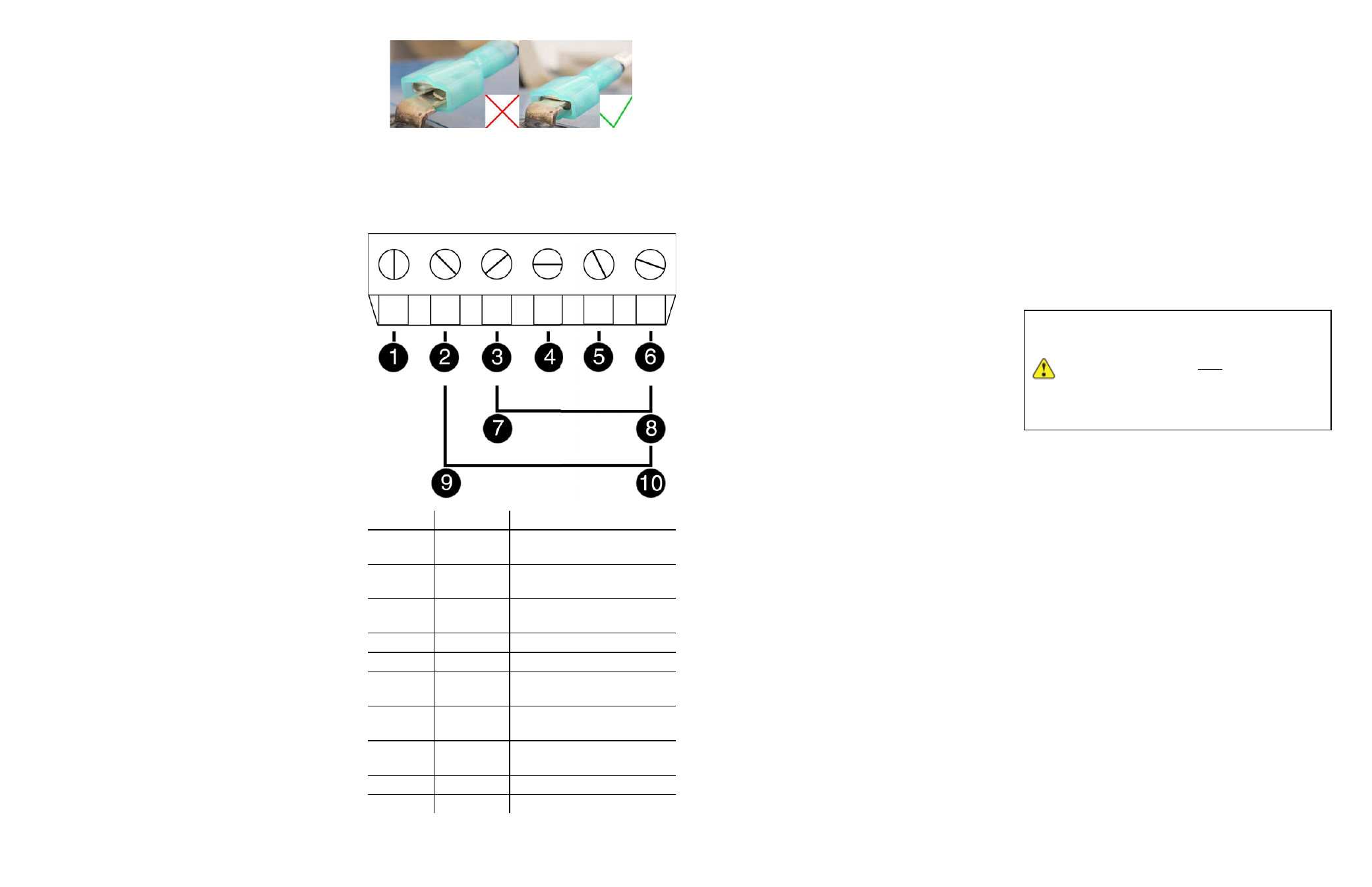
2. Plug the black (negative) leads into the black terminals of
the batteries first. Ensure that the terminal does not sit
between the lead clip and the plastic sheath, but that the
lead clip encompasses the battery terminal.
3. Plug the red (positive) leads into the red battery
terminals. Ensure that the terminal does not sit between
the lead clip and the plastic sheath, but that the lead clip
encompasses the battery terminal.
TROLL Link 100 Wiring Diagram
Number
Function
Wire
1
DC Com
(-)
Bulkhead black wire; solar
panel black wire
2
Discrete
Input
3
Discrete
Counter
4
RS485 (+)
Bulkhead blue wire
5
RS485 (-)
Bulkhead green wire
6
DC (+)
Bulkhead red wire; fuse
blue wire
7
Pulse
Count. (-)
8
Pulse
Count. (+)
9
Relay (-)
10
Relay (+)
Turning Off the Modem
1. Disconnect the white wire from the SOL+ screw
terminal.
2. Disconnect the red (positive) lead from the red battery
terminal.
3. Disconnect the black (negative) lead from the black
battery terminal.
Maintenance
Fuse Replacement
Two fuses are located on the left edge inside of the
enclosure. The left fuse connects to the internal battery,
the right fuse connects to the charger/external power. The
fuses are 2 amp, time-delay, speed-type fuses rated for
250 VAC. Replace as needed.
Enclosure Desiccant
It is extremely important to use a properly-sized
desiccant for your deployment, and to change desiccant
before the entire volume has turned pink. Use
enough desiccant to effectively keep electronics dry until
your next scheduled maintenance. Desiccant life span is
dependent on site conditions.
The enclosure contains one tube of desiccant that absorbs
moisture as it enters the enclosure through the vent tube.
Keep the vent tube clear of obstructions. Replace as
needed. An additional desiccant pack may be located at
the top of the enclosure. Replace or dry as needed.
Software Appendix
Changing Win-Situ Software Device Address
and Communication Settings
If you change an instrument's device address or other
communication settings, you must change Win-Situ
Software communication settings to reconnect and
communicate with the instrument.
1. Connect the instrument to a laptop or PC.
2. Open Win-Situ Software. When it asks "Connect to
device now?" click No.
3. In the top menu bar, click Preferences.
4. Click Comm Settings.
5. Enter instrument's device address into the Device
Address box.*
6. Ensure the correct COM port is selected in the Port
Number box. See page 3.
7. Ensure other communication settings (e. g., Baud, Data
Bits, Parity Bits, Stop Bits, Mode) match the device
settings.*
8. Click the check mark.
9. Click the Connect button in the lower right corner.
* If you do not know the device address or communication
settings for an instrument, disconnect the instrument from
the networking device. Connect the instrument directly to
the PC. Click the Reset All Devices button in the Comm
Settings window. Clicking the Reset All Devices button
restores device defaults.
If the instrument is connected to a networking
device (e.g., a TROLL Net Hub) when
Reset
All Devices
is clicked,
ALL
other
instruments connected to the networking
device are restored to default settings. Unique
addressing for the network is lost.
Any device deployed in a network must have the
appropriate device communication settings reapplied.
Selecting the Correct COM Port
If you are using a USB TROLL Com, select the correct
COM port by following the steps below. If you are using a
serial TROLL Com, the Win-Situ Software should default
to the correct COM port, which is usually COM 1.
Steps for Windows
®
7 systems.
1. Minimize the Win-Situ Software.
2. Click the Windows Start button, and open the Control
Panel.
3. Click Hardware and Sound, and open the Device
Manager.
4. Click the arrow next to Ports (COM and LPT), and
locate the USB Serial Port listing. The number listed next
to this entry is your COM port address.
Steps for Windows
®
XP systems.