Verify instrument depth, Secure the cable, Desiccant – In-Situ Level TROLL 400/500/700/700H Quick Start Guide User Manual
Page 2: Installing desiccant with twist-lock connectors, Installing outboard desiccant, 5 safety, 6 win-situ 5 software, Install win-situ 5, Connecting an instrument to the software, Safety
Information subject to change without notice. In-Situ, In-Situ logo, Baro Merge, BaroTROLL, HERMIT, iSitu, Pocket-Situ, RDO, RuggedCable, RuggedReader, TROLL, and Win-Situ are trademarks or registered trademarks of In-Situ Inc.
©
2013. All rights reserved.
A BaroTROLL Instrument can be deployed
with a non-vented instrument to compensate
level data for changes in atmospheric
pressure. Make sure the clocks on both
instruments are synchronized, and install the
BaroTROLL in a location that will never be
submerged in water.
Range
Effective Range
Usable Depth
PSIA
PSIA
kPA
Meters
Feet
30
15.5
106.9
11
35
100
85.5
589.5
60
197
300
285.5
1968
200
658
500
485.5
3347
341
1120
1000
985.5
6795
693
2273
* Effective range for psia sensors is limited by an estimated 14.5
PSI atmospheric pressure at sea level.
Non-Vented Level TROLL Instrument
Range
Usable Depth
PSIG
kPA
Meters
Feet
5
34.5
3.5
11.5
15
103.4
11
35
30
206.8
21
69
100
689.5
70
231
300
2068
210
692
500
3447
351
1153
Vented Level TROLL Instrument
Verify Instrument Depth
After you have installed the instrument, it is possible to
connect the instrument to a computer or RuggedReader,
open the software, and take a reading to verify the
installation position. If the reading confirms that the
instrument is in the correct position, you can secure it as
described below.
During log setup there was an option to "Remind Me Later"
for setting a level reference. If you set the log to remind you
later, ensure that the instrument is submerged and set the
level reference when prompted.
Secure the Cable
1
Well Dock Installation Ring
2
Kellems Grip
3
Instrument Installed in Well
Desiccant
Desiccant protects electronics from condensation, which
can cause irreparable damage and loss of data. Indicating
desiccant changes from blue to pink as it becomes
saturated with moisture.
Desiccant stages (from left)
New, nearly expired (replace now), expired
It is extremely important to use a properly-sized
desiccant for your deployment and to change desiccant
often. Desiccant should be changed before the entire
volume has turned pink, and you should use enough
desiccant to effectively keep cables, instruments, and
electrical boards dry until your next scheduled
maintenance. Desiccant life span is dependent on site
conditions.
Installing Desiccant with Twist-Lock
Connectors
1. Remove the protective dust cap from the bottom of the
desiccant pack, if applicable.
2. Remove expiring desiccant (if present) from the cable by
grasping the textured section of the cable connector in
one hand and the desiccant in the other. Twist in
opposite directions to unlock the desiccant from the
cable.
3. Attach the new desiccant pack to the twist-lock
connector on the cable.
Installing Outboard Desiccant
Vented cable must be installed with outboard desiccant to
protect the cable and instrument electronics from
condensation in high-humidity environments.
The desiccant can be removed from the vent tube, if
necessary, to trim the conductor wires. However, you must
reinstall the desiccant after trimming and connecting the
wires.
1. Cut off the knot at the bottom of the vent tube extension.
2. Firmly attach the vent tube extension to the cable vent
tube. Cover at least 6.4 mm (0.25 in.) of the cable vent
tube for a secure attachment.
3. Use the attached hook-and-loop strap to secure the
desiccant to the cable, below the stripped wires.
4. Remove the red dust cap from the black nylon cap to
allow air to reach the cable’s vent tube.
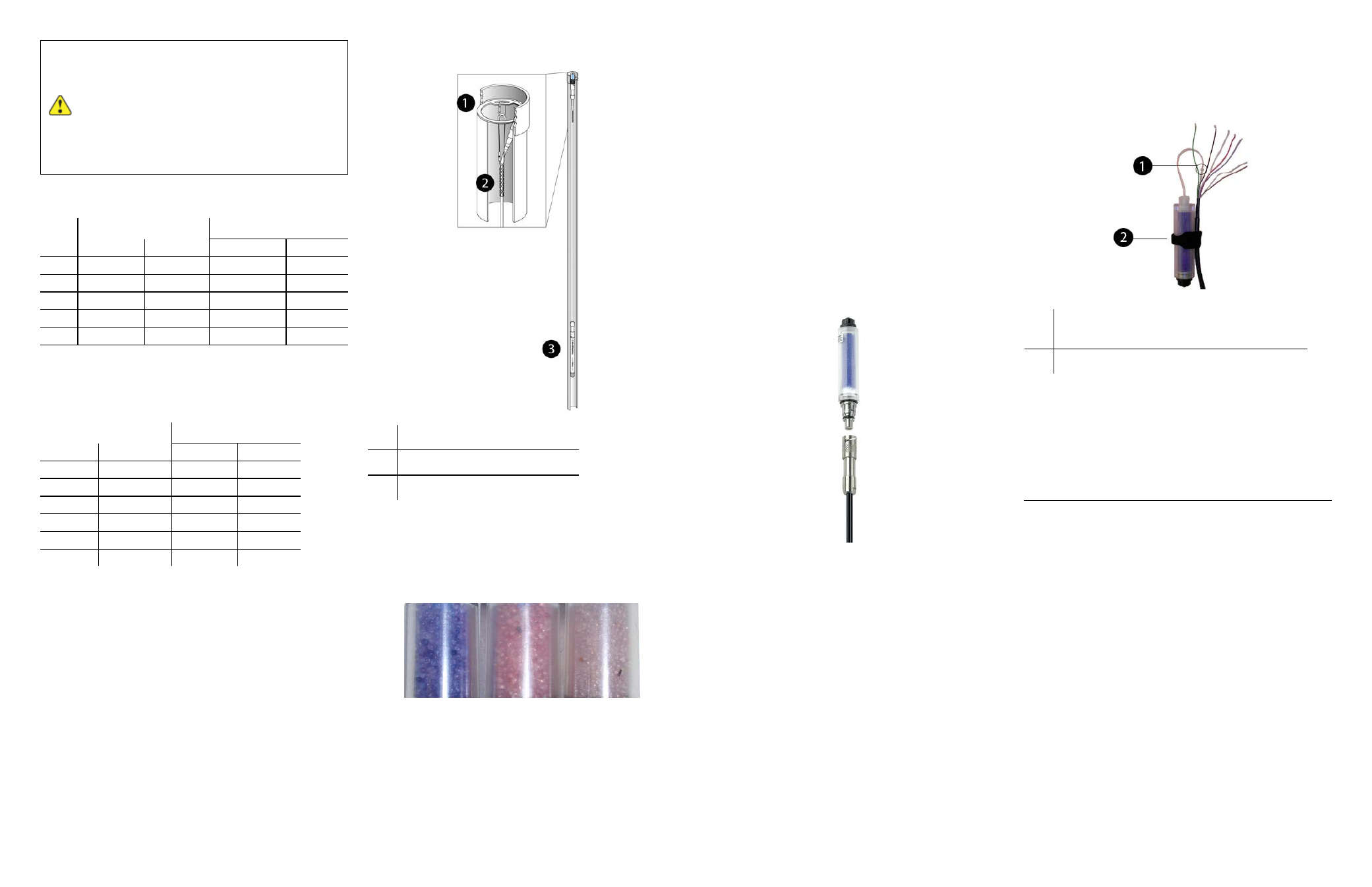
1
Outboard desiccant is attached to the cable
vent tube.
2
Desiccant is secured to the cable with a strap.
Safety
The instrument complies with all applicable directives
required by CE and the FCC and is found to comply with
EN 61326, ICES-003, and FCC Part 15 specifications.
Declarations of conformity may be found in the Operator's
Manual.
Win-Situ 5 Software
Use Win-Situ 5 with a laptop or a PC and the Aqua
TROLL, Level TROLL and Rugged TROLL Instruments.
To learn more about Win-Situ 5, refer to the Help menu.
Training videos are available on the In-Situ Inc. website
www.in-situ.com under Tech Resources.
Install Win-Situ 5
Insert the software CD that came with your product or
download Win-Situ 5 from the In-Situ website at www.in-
situ.com/software. Follow the on-screen prompts of the
Installation Wizard to complete installation.
IMPORTANT: Install COM drivers when prompted.
Connecting an Instrument to the Software
When you open Win-Situ 5 Software, you are asked if you
want to connect to your device. Click Yes. Synchronize the