GW Instek GDM-8245 User Manual
Page 8
DUAL DISPLAY DIGITAL MULTIMETER
USER MANUAL
12
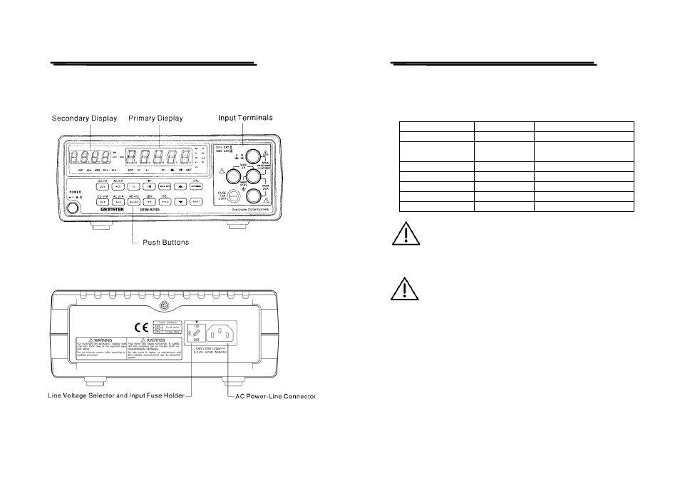
z Figure 4-1 Front Panel
z Figure 4-2 Rear Panel
DUAL DISPLAY DIGITAL MULTIMETER
USER MANUAL
13
4-6 Input overload protection
The maximum allowable input is shown as table 4-1. Please proceed
the measurement accordingly.
Table 4-1:
FUNCTION
RANGE
MAXIMUN INPUT
DCV
5V~1000V
1000Vdc or peak ac
ACV (AC+DC)
5V~1000V
1000V rms continuous &
10
7
V•Hz maximum
DCA,ACA(AC+DC)
500μA~2A
fuse protected: 2A 250V
DC,AC20A(AC+DC)
20A
no fuse protected
DC,ACmV (AC+DC)
500mV
450V dc or ac peak
OHM
all ranges
450V dc or ac peak
CAPACITANCE
all ranges
450V dc or ac peak
WARNING: To avoid shock hazard and/or instrument damage,
do not apply input potentials that exceed the input overload
limits shown in table 4-1.
4-7 Input connections to common
WARNING: To avoid shock hazard and/or instrument damage,
do not connect the common input terminal to any source of
more than 500 volts DC or peak AC above earth ground.
- GDB-03 (99 pages)
- GLA-1000 Series User Manual (111 pages)
- GLA-1000 Series Quick start guide (20 pages)
- GOS-630FC (20 pages)
- GOS-635G (36 pages)
- GOS-6000 Series (27 pages)
- GOS-6103C (30 pages)
- GOS-6100 Series (30 pages)
- GRS-6000A Series (51 pages)
- GDS-122 Installation Guide (4 pages)
- GDS-122 User Manual (52 pages)
- GDS-2000A series CAN/LIN bus User Manual (18 pages)
- GDS-2000A series Quick start guide for DS2-FGN (6 pages)
- GDS-2000A series Freewave User Manual (26 pages)
- GDS-2000A series Quick start guide for Logic analyzer option (18 pages)
- GDS-2000A series Quick start quide for DS2-LAN (2 pages)
- GDS-2000A series Option User Manual (80 pages)
- GDS-2000A series User Manual (261 pages)
- GDS-2000A series Programming Manual (272 pages)
- GDS-2000A series Single sheet for LA Quick start guide (2 pages)
- GBS-1000 Series Programming Manual (88 pages)
- GBS-1000 Series User Manual (187 pages)
- GDS-1000-U Series firmware upgrade (1 page)
- GDS-1000-U Series Programming Manual (70 pages)
- GDS-1000-U Series Quick start guide (2 pages)
- GDS-1000-U Series User Manual (133 pages)
- GDS-1000A-U Series Programming Manual (88 pages)
- GDS-1000A-U Series Quick start guide (2 pages)
- GDS-1000A-U Series User Manual (148 pages)
- GDS-3000 Series GCP-530/1030 current probe User Manual (40 pages)
- GDS-3000 Series GDP-025/050/100 differential probe User Manual (21 pages)
- GDS-3000 Series DS3-PWR Power analysis manual (37 pages)
- GDS-3000 Series User Manual (209 pages)
- GDS-3000 Series Programming Manual (103 pages)
- GDS-3000 Series DS3-SBD Serial Bus decode (29 pages)
- GDS-3000 Series GKT-100 deskew fixture User Manual (1 page)
- GDS-3000 Series GUG-001, GPIB to USB adapter User Manual (15 pages)
- GDS-300 Series User Manual (188 pages)
- GDS-300 Series Programming Manual (139 pages)
- GDS-300 Series Quick start guide (21 pages)
- GRF-3300 Series Student Manual (26 pages)
- GRF-3300 Series Teacher Manual (26 pages)
- GRF-1300A (124 pages)
- GSP-810 User Manual (40 pages)
- GSP-810 Software Manual (3 pages)