GW Instek GPM-8212 User Manual
Page 11
POWER METER
USER MANUAL
17
z PT Ratio setting
1) Press the button of [VPT] to appear the letters of PT on the window 2,
window 3 indicates the previous setting parameter, and window 1
appears "————". If no further action, it will return to previous test
mode within 5 seconds, or press [Å] key directly.
2) Then proceed the following steps to set the desired parameters, such as
1000:
— Press [1] to appear 1---.
— Press [0] to appear 10--.
— Press [0] to appear 100-.
— Press [0] to appear 1000.
3) If there is any mistake, press [Å] key to erase front error numbers.
4) After pressing [ENTER] to save the information, return to test mode.
z CT Ratio setting
1) Press the button of [ACT] to appear the letters of CT on the window 2,
window 3 indicates the previous setting parameters, and window 1
appears "————". If no further action, it will return to previous test
mode within 5 seconds, or press [Å] key directly.
2) Then proceed the following steps to set the desired parameters, such as
1000:
— Press [1] to appear 1---.
— Press [0] to appear 10--.
— Press [0] to appear 100-.
— Press [0] to appear 1000.
3) If there is any mistake, press [Å] key to erase front error numbers.
4) After pressing [ENTER] to save the information, return to test mode
POWER METER
USER MANUAL
18
6. RS232 COMMUNICATION INTERFACE
z Introduction
The instrument can be operated from a host (eg. A terminal controller,
computer, PLC…) by sending commands through a computer interface on
the rear panel.
z Communication parameter
Baudrate : 1200, 2400, 4800, 9600 bps.
Parity : None
Data bits
: 8
Stop bit
: 1
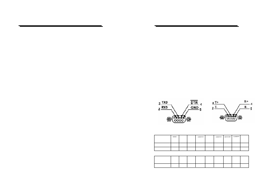
z Wire drawing: Located in the rear panel of GPM-8212.
RS-232 RS-485
Pin 232:
SIGNAL
CD RXD TXD DTR GND DSR RTS CTS
RI
9
PIN 1 2 3 4 5 6 7 8 9
25PIN 8 3 2 20 7 6 4 5 22
Pin 485:
SIGNAL
NC
TxD
-
TxD
+
RxD
+
RxD
-
NC
NC
NC
NC
PIN
No.
1 2 3 4 5 6 7 8 9