Relay activation and configuration, Figure 19 da4 / analog input activation – Detcon 1600A-N1P User Manual
Page 21
1600A-N1P
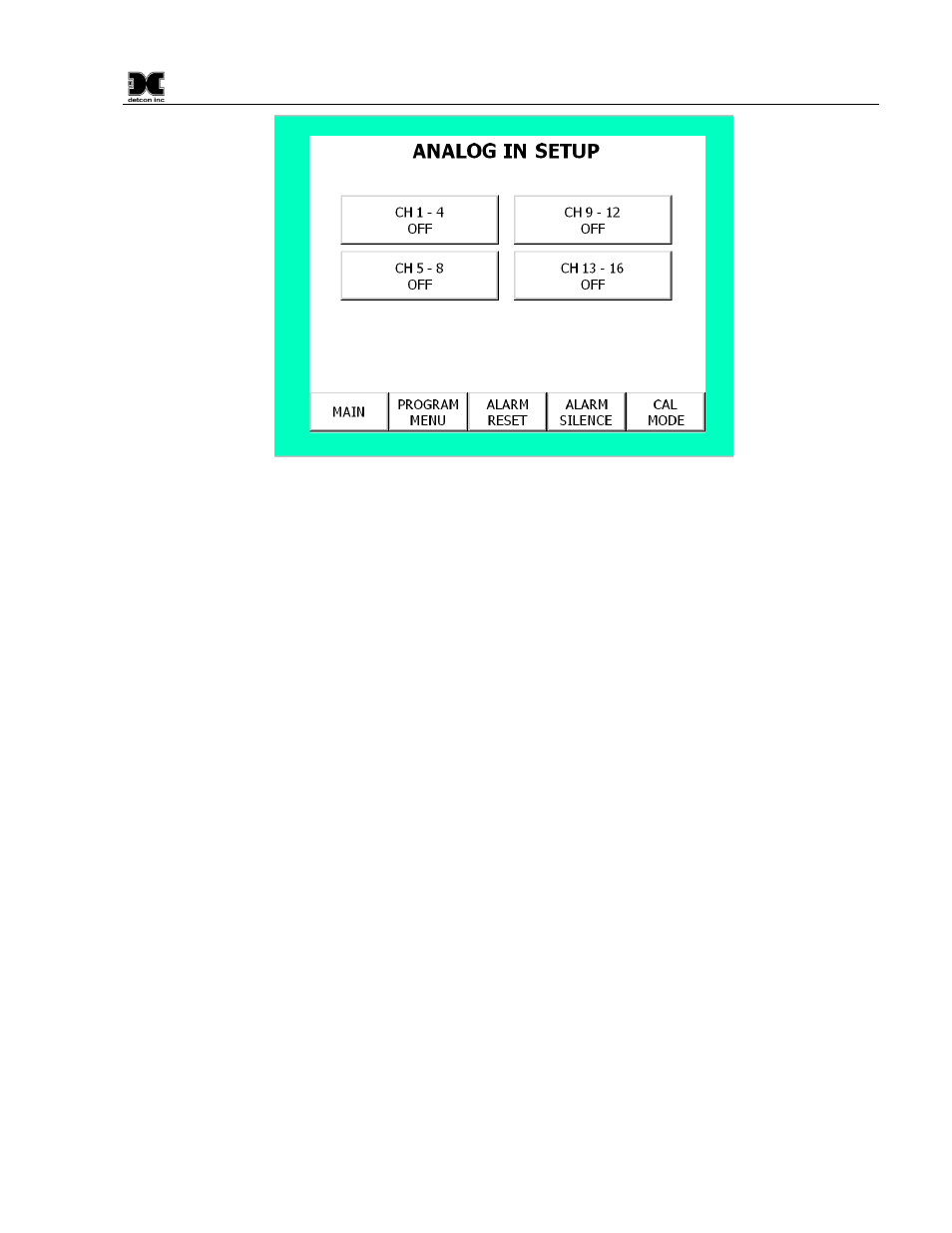
Figure 19 DA4 / Analog input Activation
Example: In this example, the 1600A is to be set up for two Model DA4 input modules. Make sure that the
switch setting for the first Model DA4 module is set to 01, representing the first gas input and is wired to
terminal connection #1, for position 1 on the module’s wiring connector. The DA4 addresses would be as
follows:
CH #
DA4 Address
01 thru 04
01
05 thru 08
05
4.1.3 Relay Activation and Configuration.
The relay output setup is similar to the gas channel setup. The default setting for the relays as shown in
is for all relays to be in “Off” status. Press the “CH1-4 OFF” key for the CH1-4
box to use the first RL4 module. Note the block now shows as “CH1-4 ON”. The second part of Relay Setup
requires the decision of how the individual relay contacts will be configured. Press the block labeled
“CONFIGURE CH 1-4”, and a relay setup screen will appear. Each relay must be selected as latching or non-
latching, energized or non-energized, and silenceable or non-silenceable. These selections are shown in three
small blocks to the right of the Relay # input. Make selections by pressing the buttons on screen (
). Entries are saved automatically when exiting the screen by pressing MAIN or
Device Setup. Continue this sequence for all other relays.
RL 4 Module addresses:
Relay 1-4
41
Relay 5-8
45
Relay 9-12
49
Relay 13-16
4D
1600A-N1P Instruction Manual
Rev. 0.1
Page 17 of 40