Figure 9 model da-4 and 4-20ma gas sensors, Figure 10modbus™ gas sensor connections – Detcon 1600A-N1P User Manual
Page 14
1600A-N1P
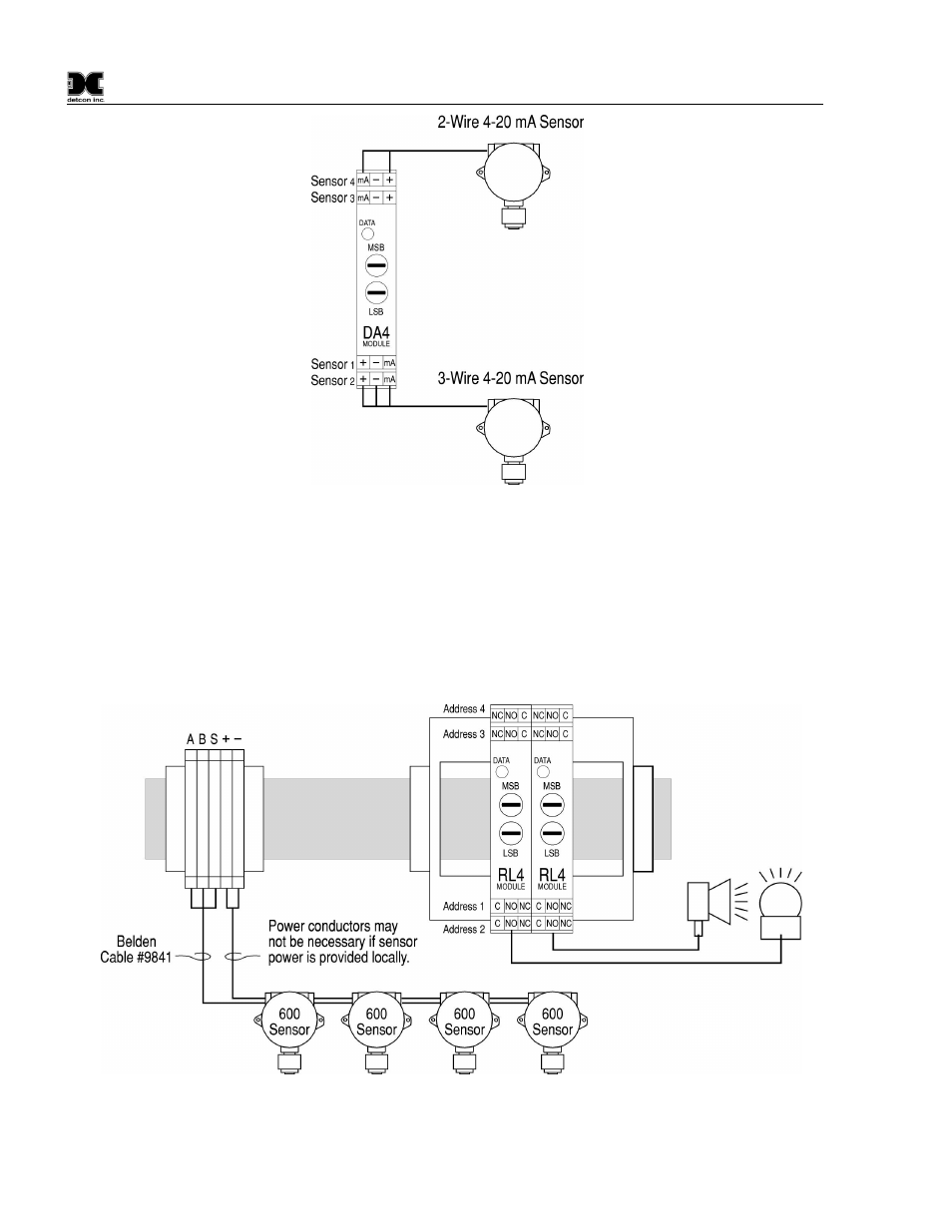
Figure 9 Model DA-4 and 4-20mA Gas Sensors
RS-485 Modbus Gas Sensors
Connect the five wires from the Modbus™ gas sensors (Detcon Model 600 and Model 700 Series types) to the
din rail mounted terminals labeled RS-485 “A”, “B”, and “Shld” and VDC “+” and “-”. Note: the controller
power supply is only capable of handling 3 Amps accumulative. If the external sensors plus the controller’s
internal modules exceeds this rating, only three wires (RS-485 “A”, “B”, and “Shld”) should be used and a
remote DC power source should be utilized to provide DC power for the remote mounted gas sensors.
NOTE: A 120
Ω end of line resistor should be installed on the last gas sensor in the serial loop to enhance
communications reliability.
Figure 10Modbus™ Gas Sensor Connections
1600A-N1P Instruction Manual
Rev. 0.1
Page 10 of 40
- 12B (16 pages)
- FL-10 (7 pages)
- 10C Facilities (18 pages)
- 10C (29 pages)
- 10B (10 pages)
- 1212-N4X (9 pages)
- 812-N4X (9 pages)
- 1212B (5 pages)
- 612B (5 pages)
- 1610-N4X (28 pages)
- 1010-N4X (14 pages)
- 610-N4X (12 pages)
- 1610-N1 (4 pages)
- 810-N1-24VDC (10 pages)
- 410-N1-24VDC (4 pages)
- MCX-32-N1P (55 pages)
- RD-64X-N4X (41 pages)
- 880RA-N4X (36 pages)
- 880RA-N4X (23 pages)
- 880A-N1R (45 pages)
- 880A-N4X (50 pages)
- 880A-N4X (43 pages)
- X40-08-N4X (70 pages)
- 240 (33 pages)
- SW-AV1-N4 (12 pages)
- SW-AV2-DV1 (12 pages)
- A1V1 (9 pages)
- RXT-300 (47 pages)
- RXT-320 (31 pages)
- CXT-N4X (28 pages)
- SW-HMI-32-N4X (24 pages)
- SW-V1-DV2 (11 pages)
- SW-AV1-DV1 (14 pages)
- SW-AV2-DV2 (12 pages)
- SW-AV1-DV2 (12 pages)
- SmartWireless CX (33 pages)
- SmartWireless CXT (49 pages)
- CX-IR (38 pages)
- CX-DM (44 pages)
- CXT-IR (48 pages)
- CXT-DM (56 pages)
- P-1000 (28 pages)
- 1000 (32 pages)
- 1000_CO2 (32 pages)
- 1000_H2S (34 pages)