Initial power checks, Figure 13 location of termination jumper (jp6), 6 (term) figure 13. this – Detcon 1600A-N1P User Manual
Page 16: 5 initial power checks
1600A-N1P
• Belden 9841 cable is recommended for a single cable providing serial communications only.
Ground the cable shielding at the Model 1600A-N1P Controller only. Other points of grounding may
cause a ground loop, and induce unwanted noise on the RS-485 line, which in turn may disrupt
communications.
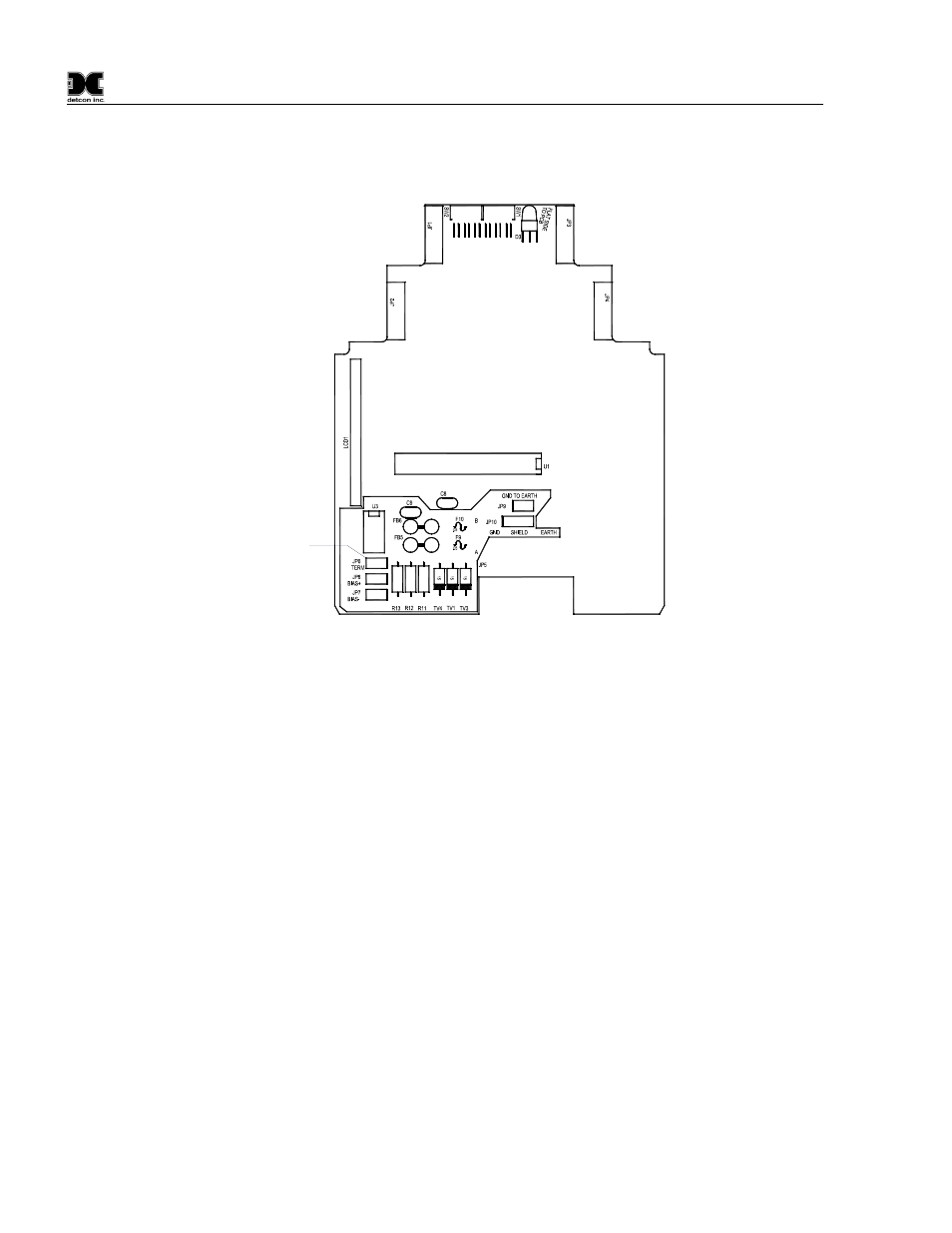
Jumper
located on
component
side of PCB
Figure 13 Location of Termination jumper (JP6)
3.5 Initial Power Checks
Before applying power, make sure that all I/O Modules are correctly installed and that all wiring connections
between I/O modules and external devices are made correctly.
NOTE: Applying power with devices hooked up incorrectly may cause damage.
Turn the applicable AC Breaker and DC Breaker switches to the ON positions. Verify that the main touch-
screen LCD comes on displaying gas readings. After 5 seconds, verify that all the I/O modules are being
polled by observing a sequence of blinking LED’s on the I/O Modules representing successful serial
communication.
NOTE: The polling of the input devices takes place more frequently than the communications to the relay
output devices. The sequence of polling communication will follow the order of the I/O device switch
addresses.
1600A-N1P Instruction Manual
Rev. 0.1
Page 12 of 40