1600a interface board, Figure 6 1600a interface pca, J1 j3 j4 j5 – Detcon 1600A-N1P User Manual
Page 10
1600A-N1P
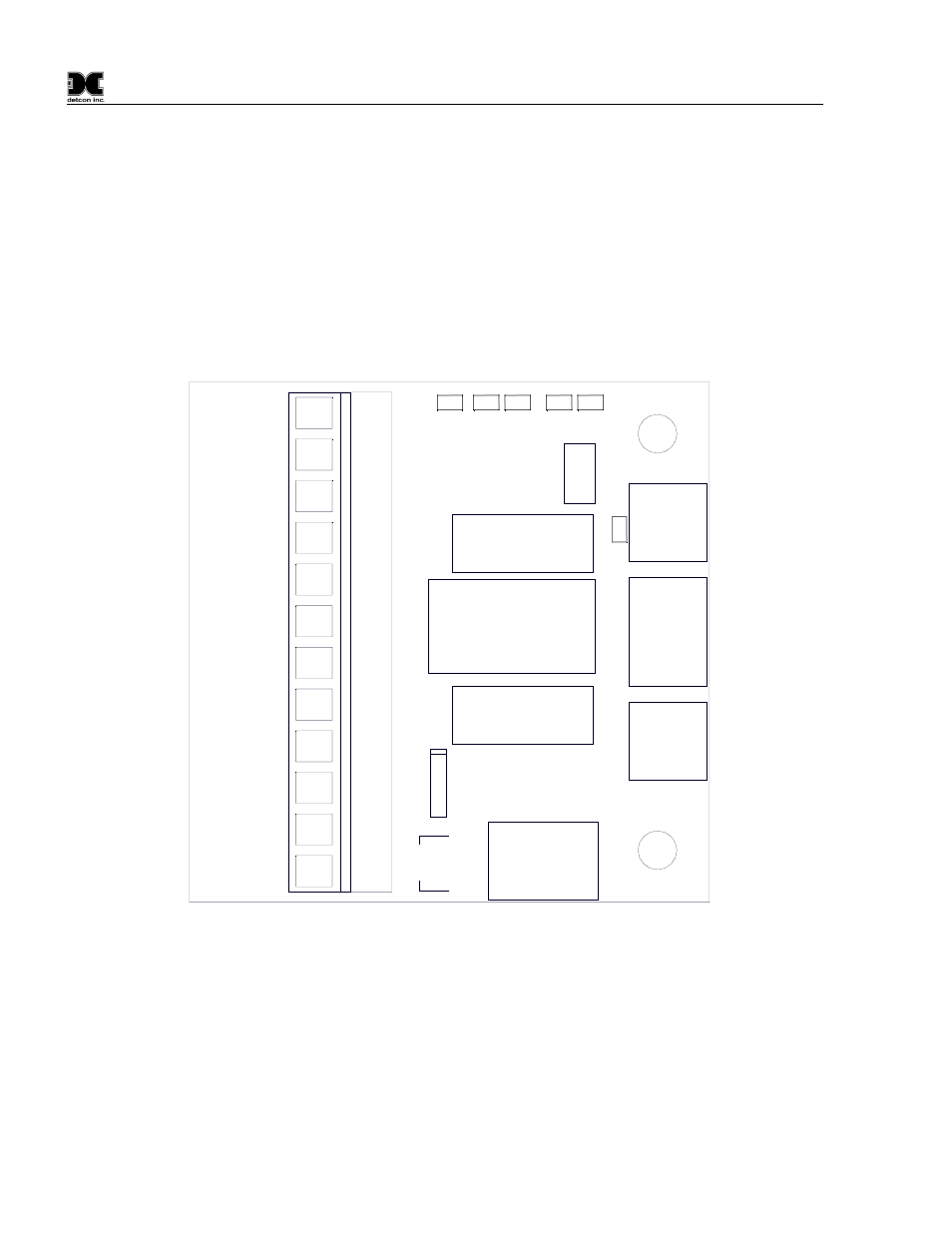
3.1 1600A Interface Board
The 1600A Interface PCA is connected to a set of Terminal Blocks on the DIN Rail (
.) The Terminal Blocks are labeled “NO
COMM” “C”, “NO” and “NC”. The 1600A Interface PCA, mounted on the inside of the top panel of the
enclosure, will de-energize the on-board relay in the event there is a ‘No Communication Fault’ condition with
any activated device. A ‘No Communication Fault’ condition will ‘short’ the common and normally closed
contacts, and creates an open between the normally open and common relay contacts of the on-board relay.
This is required for fail-safe operation. There is a two-minute delay before any active device will trigger a no
communication condition.
Figure 6 1600A Interface PCA
Figure 7 Interconnect Wiring Diagram
J1
J3
J4
J5
U1
U2
1
2
3
4
5
6
7
8
9
10
+
-
NC
NO
C
+
-
A
B
SHLD
Sh
ld
B
A
11
12
XPSN
PWR
XPSN
GND
SCRN
PWR
SCRN
GND
PLC
PWR
PLC
GND
NO
COM
FLT
RST
POWER IN
FAU
LT
/
NO CO
M
RESET
RS 4 8 5
FAULT
NO COMM
RST
R
G R
G R
G
1600A-N1P Instruction Manual
Rev. 0.1
Page 6 of 40