Figure 11 model rl-4 relay module, Figure 12 model ao-4 module – Detcon 1600A-N1P User Manual
Page 15
1600A-N1P
Relay Output Contact Modules
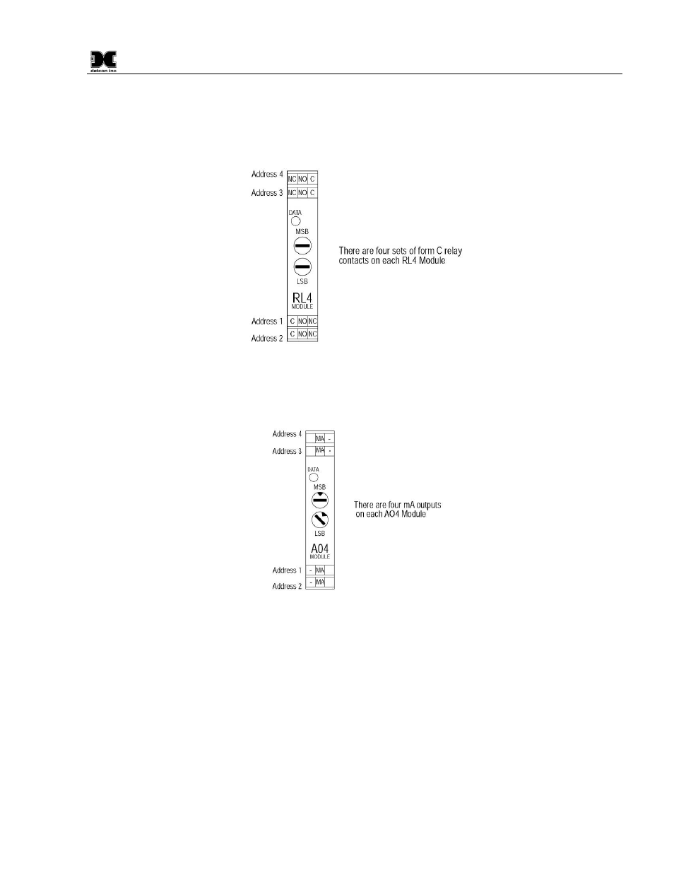
There are four ‘Form C’ 5 Amp relay contacts in each Model RL4 module. These can be used to fire
annunciating devices or as signal inputs to other control devices. Connect to the relay contacts of the Model
RL4 module as shown Figure 11. Note that the Amp rating of the relay contact should not be exceeded.
Figure 11 Model RL-4 Relay Module
4-20mA Output Modules
There are four 4-20mA outputs in each Model AO-4 module. These can be used as signal inputs to other
control devices. Connect to the AO-4 modules as shown in
Figure 12 Model AO-4 Module
General Wiring Notes:
When I/O Modules are located at a remote distance from the controller, an end-of-line terminating resistor
is required to enhance communications reliability. Identify the last I/O Module in the loop, and open the
module casing using the clip release points. Locate and install the jumper on JP6 (TERM) Figure 13. This
adds a 120
Ω resistor to the end of the line. If applicable, add a 120Ω resistor to the last Modbus™ gas
sensor.
Follow generally accepted guidelines for RS-485 serial networks. Do not wire I/O Modules and/or
Modbus™ gas sensors in long-distance ‘T-Tap’ configurations. Stay with direct serial configurations. See
Appendix A for serial communications configuration guidelines.
Use Detcon Recommended cabling whenever possible.
• Belden P/N 1502P cable is recommended for a single cable providing serial communications and
power.
1600A-N1P Instruction Manual
Rev. 0.1
Page 11 of 40