1 cxt sensor registers, 1 sensor faults – register 0005, Cxt sensor registers – Detcon CXT-DM User Manual
Page 34
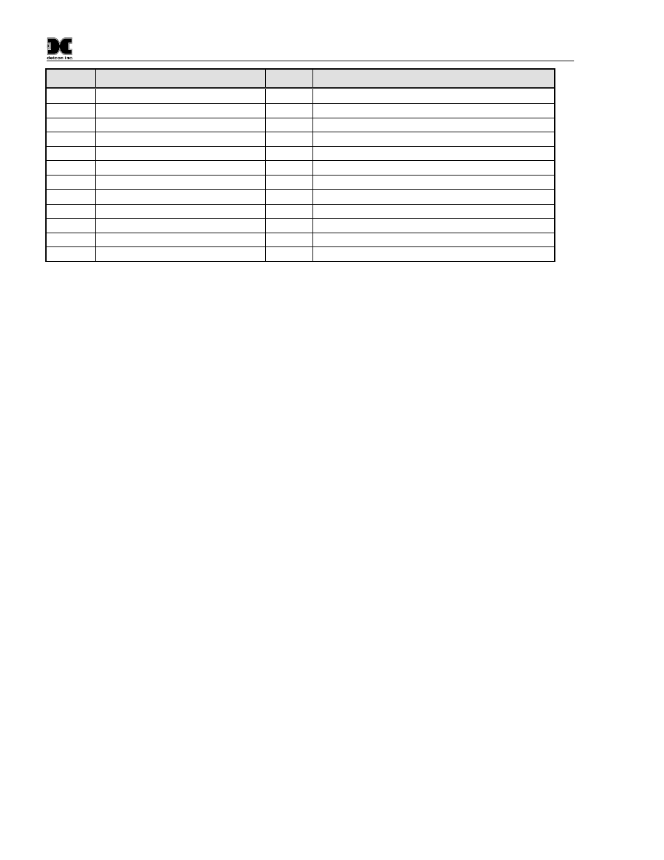
Model CXT-DM
Offset
Name
R/W
Comment
8199
Battery Life in Percent
R
Smart Battery Life remaining in percent
8200
Battery Life in Minute
R
Smart Battery Life remaining in minutes
8201
Wireless Controller Version
R
same as register 0027
8202
RF Update Rate
W
Number of seconds to power down transceiver
8203
Control
R/W
Wireless Control
8204
Status
R
Wireless Status
8205
Input Voltage
R
Smart Battery voltage or Input Voltage to A/D
8206
Battery Error Count
R/W
Smart Battery read error count if detected
8207
Reserved
--
8208
Timestamp[0]
R
Time since power applied -- Seconds High
8209
Timestamp[1]
R
Time since power applied -- Seconds Low
8210
Timestamp[2]
R
Time since power applied -- Milliseconds
4.2.1 CXT Sensor Registers
4.2.1.1
Sensor Faults – Register 0005
The sensor fault status register consists of High and Low Status Bits. These bits are set/reset as faults occur or
are cleared. Each bit has a particular meaning:
Register #
High Byte
Low Byte
0005
Status Bits
Status Bits
Bits read as 0 are FALSE; bits read as 1 are TRUE
Status Bits High Byte:
Bit 15 – Reserved
Bit 14 – Calibration Mode
Bit 13 – Reserved
Bit 12 – Zero Fault
Bit 11 – Range Fault
Bit 10 – Reserved
Bit 9
– Clearing Fault
Bit 8 – Reserved
Status Bits Low Byte:
Bit 7 – Sensor Fault
Bit 6
– Processor Fault
Bit 5
– Memory Fault
Bit 4
– Reserved
Bit 3
– Reserved
Bit 2 – Temperature Fault
Bit 1 – Auto Span Fault
Bit 0
– Global Fault
CXT-DM Instruction Manual
Rev. 1.6
Page 30 of 52