2 terminal connections 4-20ma and rs-485, Terminal connections 4-20ma and rs-485, Figure 8 sensor wire connections – Detcon CX-DM User Manual
Page 12
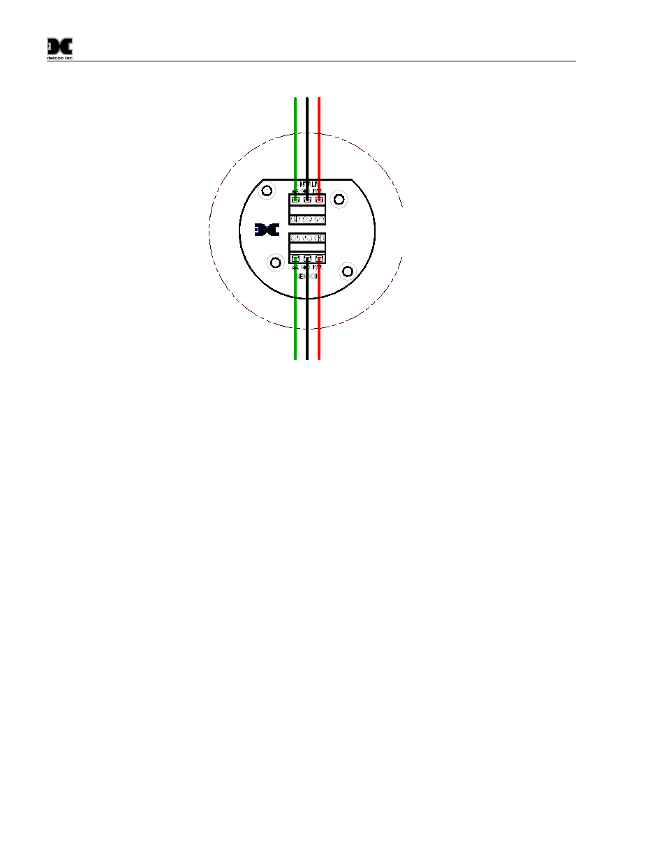
Model CX-DM
mA
(+)
(-)
Wiring to
Sensor Assembly
R
ed
Gr
ee
n
B
la
ck
Explosion
Proof
Junction Box
(+)
mA
(-)
Wiring to
Controller
R
ed
Gr
ee
n
B
la
ck
Detcon Inc.
Rev. 1
440-005208-000
MODULE
PROTECTION
TRANSIENT
Figure 8 Sensor Wire Connections
a) Remove the junction box cover. Identify the terminal blocks for customer wire connections.
b) Observing correct polarity, terminate the 3-conductor 4-20mA field wiring (+, -, mA) to the sensor
assembly wiring in accordance with the detail shown in Figure 8.
c) Replace the junction box cover.
2.6.2 Terminal Connections 4-20mA and RS-485
1. Remove the junction box cover.
2. Connect the incoming 24V to the terminal labeled "+" and 24V return to the terminal labeled "–". Connect
the mA output to the “mA” terminal and the Modbus signals (if used) to the “A” and “B” terminals. Note:
the “Y” terminal is not used.
3. Replace the junction box cover after Initial Start Up (Section 2.7).
CX-DM Instruction Manual
Rev. 1.3
Page 8 of 40