6 field wiring, 1 terminal connections 3-wire 4-20ma, Field wiring – Detcon CX-DM User Manual
Page 11: Terminal connections 3-wire 4-20ma, Table 1 protection vs. wire gauge
Model CX-DM
CAUTION
Do not apply system power to the sensor until all wiring is properly terminated
(Section 2.7).
2.6 Field Wiring
Detcon Model CX-IR sensor assemblies require three conductor connections between power supplies and host
electronic controller’s 4-20mA output. Wiring designations are + (DC), – (DC), and mA (sensor signal.
Maximum wire ohmic resistance between sensor and 24VDC source is defined below. Maximum wire size for
termination in the Detcon J-Box accessory is 14 gauge.
Max Resistance drop on red and black wire is 10 ohms. This considers wire diameter, wire length and
maximum operation temperature.
Max loop load resistance between green and black wire is 500 ohms. Minimum loop load resistance between
green and black wire is 100 ohms. This is considers wire diameter, wire length, max operating temperature
and selected termination resistor.
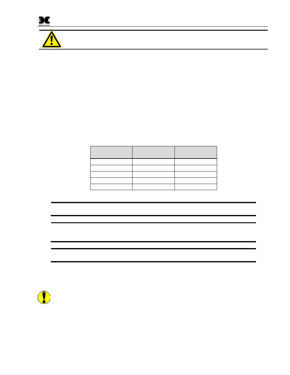
AWG
Wire Dia.
Over-Current
Protection
22
0.723mm
3A
20
0.812mm
5A
18
1.024mm
7A
16
1.291mm
10A
14
1.628mm
20A
Table 1 Protection vs. Wire Gauge
NOTE 1: Wiring table is based on stranded tinned copper wire and is designed to serve as a
reference only.
NOTE 2: Shielded cable is required for installations where cable trays or conduit runs include
high voltage lines or other possible sources of induced interference. Separate conduit runs are
highly recommended in these cases.
NOTE 3: The supply of power should be from an isolated source with over-current protection
as stipulated in table.
2.6.1 Terminal Connections 3-Wire 4-20mA
CAUTION: Do not apply System power to the sensor until all wiring is properly terminated. Refer to
Section 2.5 Initial Start Up
CX-DM Instruction Manual
Rev. 1.3
Page 7 of 40