5 serial clock & serial data line, 6 programming data, clock & reset, 0 system operation – Detcon RXT-300 User Manual
Page 21: Serial clock & serial data line, Programming data, clock & reset, System operation
RXT-300 SmartWireless™
RXT-300 Wireless IM
Rev. 2.0
Page 15 of 41
reading will reach a maximum of 2048 for currents greater than 20mA. Electrically the 4-20mA interface
supports 2-wire and 3-wire devices.
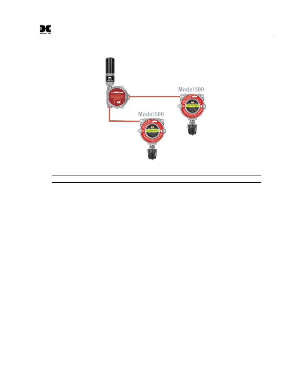
Figure 14 Up to two Sensors using two 4-20mA Interfaces
NOTE: The 4-20mA inputs do NOT support 4-wire implementations
2.3.5 Serial Clock & Serial Data Line
This is the I
2
C interface for the transceiver consisting of a serial clock (SCL) and serial data line (SDA). These
are used to monitor the status of the battery pack (if installed).
2.3.6 Programming Data, Clock & Reset
These connections are used to program the RXT-300 transceiver and should be used by Detcon personnel
only.
3.0 System Operation
The gas detection system built with the RXT-300 SmartWireless™ Transceiver operates similar to one using a
single Modbus™ controller that polls (queries) sensors connected to it. Generally upon each poll of a sensor,
data is collected, stored and processed for alarm conditions that are set by the user. If an alarm is detected the
controller activates alarms to alert the user.
In a system using the RXT-300 SmartWireless™ Transceiver, sensors that are attached to a RXT-300 as part
of a Sensor Station are located at different physical locations around the site. Data must be collected from all
of these sensors as if they were wired to a single controller. In addition to sensor data, RXT-300 status such as
battery life and status of the wireless communication between the RXT-300s must be collected. The data for
the whole system is collected by every RXT-300 on the network so that each RXT-300 has a complete picture
of the system. This allows every RXT-300 to operate independently in processing system wide alarm
conditions and allows a HMI Station to display information for the whole system.
To facilitate this, the RXT-300s with sensors attached will poll their own sensors, collect the data and process
the data for alarm conditions and store it locally. It operates essentially like a Modbus™ controller for its own
sensors. To gather the information from across the network, one of the RXT-300s is automatically chosen to
become the Master of all the RXT-300s of the network and will poll each RXT-300 on the network. Upon