Table 1 extension cable wire identification – Detcon RXT-300 User Manual
Page 17
RXT-300 SmartWireless™
RXT-300 Wireless IM
Rev. 2.0
Page 11 of 41
diagram in Figure 11. Reference Table 2 RXT-300 Transceiver Wire Identification for color code
identification.
NOTE: Wires that are not used should be individually capped off and secured out of the way
in the T-Outlet box so that they are not exposed to any active components, power, or ground.
7. Reconnect these 3 Phoenix connectors to their corresponding places back on the 8-position terminal
board with Ground.
8. Measure out the cable to be used for the extension cable to be no more than 15 feet long. Feed one end of
the cable through a ¾” NPT cord connector (cable gland) and then into the ¾” NPT hole located on the
bottom of the remote J-Box.
9. Connect the cable wires of the extension cable to the remaining three 4-pin Phoenix connectors from step
6 per the wiring diagram in Figure 11. Reference Table 1 Extension Cable Wire Identification for
color code identification.
10. Reconnect these 3 remaining Phoenix connectors to their corresponding places back on the 8-position
terminal board with Ground and thread the ¾” NPT cord connector to the bottom of the remote J-Box.
11. Install the J-Box cover of the remote J-Box.
12. Feed the other end of the cable through another ¾” NPT cord connector and then into the ¾” NPT hole of
the T-Outlet box connected to the J-Box housing the Model 100 Terminal Board.
13. Connect the cable wires to the 6-pin Phoenix connector from step 3 per the wiring diagram in Figure 11.
Reference Table 1 Extension Cable Wire Identification for color code identification.
14. Reconnect the 6-pin Phoenix connector back to J1 of the Model 100 Terminal Board and thread the ¾”
NPT cord connector to the T-Outlet box.
NOTE: Color coding of the cable will no longer match the color coding on the Model 100
Terminal Board for the J1 connector.
NOTE: Programming of RXT transceiver from the Model 100 Terminal Board will be
disabled.
15. Plug battery pack back in place and reinstall the J-Box cover from step 1.
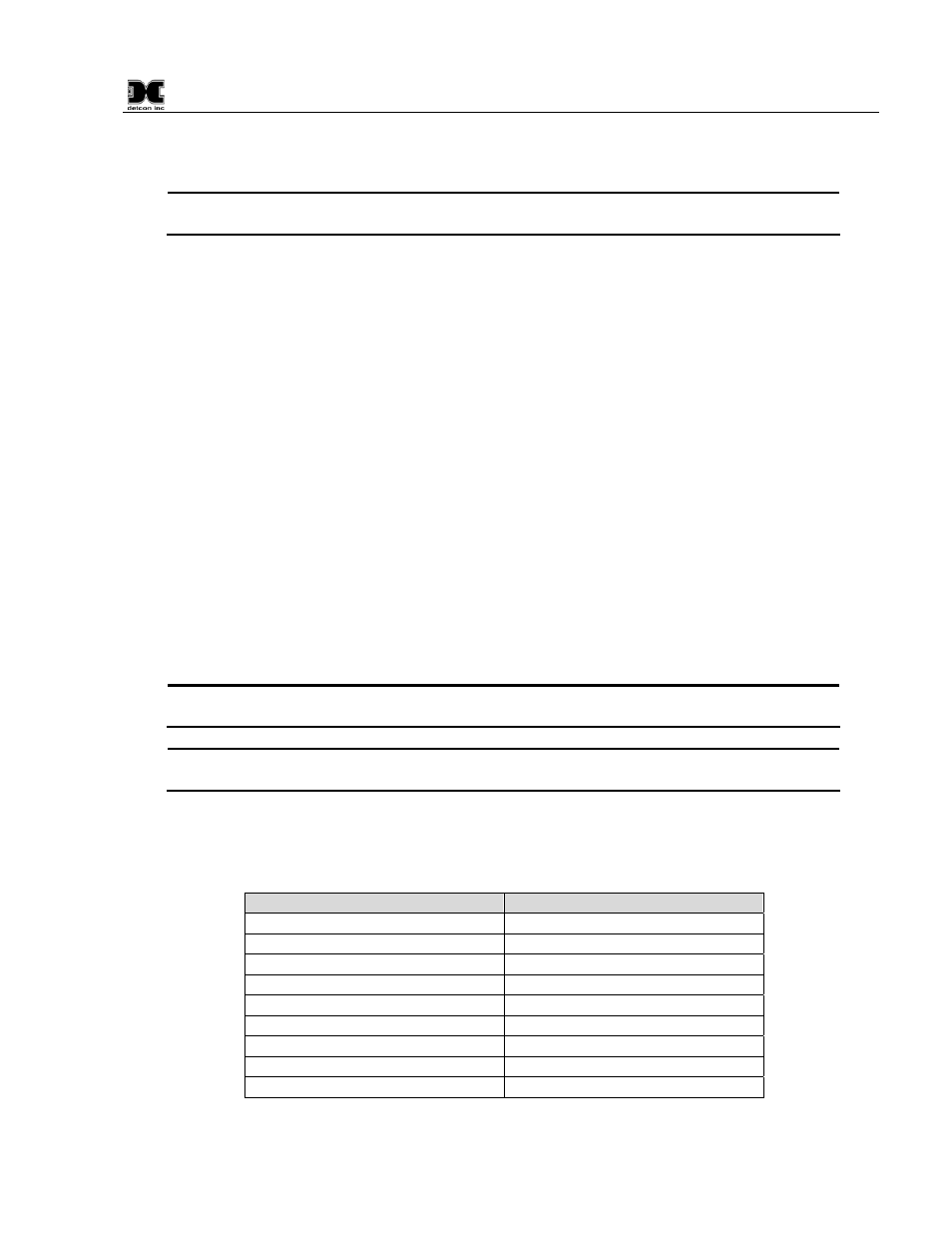
Table 1 Extension Cable Wire Identification
Function
Color Reference
VDC Power (+)
Orange/White
VDC Return (-)
Green/White
Modbus A (+)
Blue/White
Modbus B (-)
White/Blue
Serial Clock (SCL)
White/Green
Serial Data Line (SDA)
White/Brown
Common Ground
White/Orange
Common Ground
Brown/White
Drain Wire
Bare (No Color)