Detcon RXT-300 User Manual
Page 16
RXT-300 SmartWireless™
RXT-300 Wireless IM
Rev. 2.0
Page 10 of 41
NOTE: Programming of RXT transceiver from the Model 100 Terminal Board will be
disabled.
Blu (Modbus A)
Wht (Modbus B)
Red (Pwr +)
Wht/Vio (Prog Reset)
Wht/Grn (Prog Data)
Wht/Blu (Prog Clock)
Wht/Blk (Serial Clock)
Wht/Brn (Serial Data)
Blk (Gnd -)
Wht/Orn (Gnd -)
Brn/Wht (Gnd -)
Drain Wire
Wht/Brn (Serial Data)
Blu/Wht (Modbus A)
Wht/Blu (Modbus B)
Orn/Wht (Pwr +)
Grn/Wht (Gnd -)
Wht/Grn (Serial Clock)
8-Position Terminal
Board with Ground
Model 100
Terminal Board
Extension Cable
(Belden 1421A)
RXT-300
Transceiver Wiring
4-Pin Phoenix
Connectors
6-Pin Phoenix
Connector
4-Pin Phoenix
Connectors
S E N S O R /
H M I
R
B K
W
B U G N
J 2
B U
W
B K
R
W /
W /
B R
B K
W I R E -
L E S S
J 1
J 4
J 6
J 8
J 3
T P 2
m A
-
+
+
-
S A
W B
W A S B
J 7
T
P
1
1
2
3
2
3
4
5
6
7
1
E x t e r n a l D C
P o w e r I n
7 - 3 0 V D C
S p a r e M o d B u s
R X T - 3 0 0 T r a n s c e i v e r
S l a v e D e v i c e / H M I /
M a s t e r C o n t r o l l e r
R X T P r o g
I n t e r f a c e
L o o p P o w e r e d
L E D D i s p l a y
R
X
T
P
r
o
g
P
o
r
t
︵
D
e
t
c
o
n
U
s
e
O
n
l
y
︶
J 5
S m a r t B a t t e r y P a c k
W /
B U
W /
G N
W / V
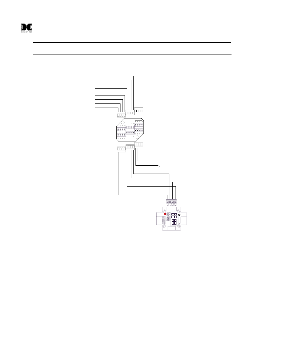
Figure 11 Wiring Diagram for Remote RXT-300 Transceiver Mounting
Remote Mounting Steps
1. Remove the J-Box cover of the RXT-300 wireless transceiver assembly.
2. If the wireless transceiver assembly has the Smart Battery Pack, unplug the battery pack from the
terminal board by pulling the battery pack out of the junction box.
3. Identify the J1 6-pin Phoenix connector and the J8 3-pin Phoenix connector on the Model 100 Terminal
Board and disconnect from the board. Remove all transceiver wire connections from the connectors.
Reconnect the 3-pin connector to its corresponding place and save the 6-pin connector for step 13.
4. Use a wrench at the bottom section of the RXT transceiver and unthread the RXT until it can be removed.
5. Feed the RXT transceiver wires through the ¾” NPT hole of the remote T-Outlet box connected to the
remote J-Box and thread the transceiver into the remote T-Outlet box until tight.
6. Remove all 6 of the 4-pin Phoenix connectors from the 8-position terminal board with Ground in the
remote J-Box and connect the RXT transceiver wires to 3 of the Phoenix connectors per the wiring