2 modbus™ a & b, 3 alarm 1-4, Modbus™ a & b – Detcon RXT-300 User Manual
Page 19: Alarm 1-4, Table 3 wire gauge vs. distance, Table 3, Wire gauge vs. distance
RXT-300 SmartWireless™
RXT-300 Wireless IM
Rev. 2.0
Page 13 of 41
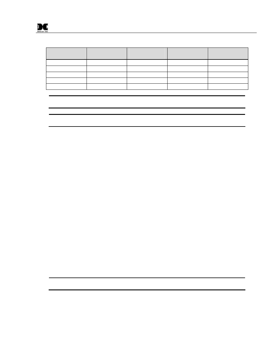
Table 3 Wire Gauge vs. Distance
AWG
Wire Dia.
Meters
Feet
Over-Current
Protection
22 0.723mm 700 2080 3A
20 0.812mm
1120 3350 5A
18 1.024mm
1750 5250 7A
16 1.291mm
2800 8400 10A
14 1.628mm
4480 13,440 20A
NOTE: Wiring table is based on stranded tinned copper wire and is designed to serve as a
reference only.
NOTE: The supply of power should be from an isolated source with over-current protection
as stipulated in table. The output voltage range must be between 7-30VDC.
Before applying power, make sure that all wiring is correct. Not all wires from the wireless transceiver are
used in most configurations. Wires that are not used should be individually capped off and secured out of the
way in the T-Outlet that mounts the transceiver to the J-Box/condulet. This prevents exposure to any active
components, power or ground.
2.3.2 Modbus™ A & B
The RXT-300 transceiver features a Modbus™ compatible communication port. The connections are
Modbus™ A (blue wire) and Modbus™ B (white wire) and are polarity dependent. Modbus™
communication is accomplished by two wire half duplex RS-485, 9600 baud, 8 data bits, 1 stop bit, no parity,
through the transceiver’s connection to the Modbus™ device. It is necessary to set a Modbus address for the
RXT-300 unless operating in transparent mode.
2.3.3 Alarm 1-4
Each RXT-300 wireless transceiver provides outputs for up to four alarms (Alarm 1, Alarm 2, Alarm 3 and
Alarm 4) which can drive relays on custom terminal boards provided by Detcon. The outputs are controlled
by the RXT-300 based upon the configuration and current alarm state of the whole network. The outputs are
open drain and rated for up to 300mA at 50V (See Figure 12). They are not intended to drive alarm devices
directly, but rather to drive relay coils (interposing relays) which in turn will drive a higher current output.
When using interposing relays, the customer must protect the RXT-300 Alarm outputs against the voltage
spike that can be over 1000V when the relay is de-energized. This voltage spike will damage the Alarm output
since it is well over the rated maximum voltage of 50V and will cause the output to fail. A transient protection
diode (1N4001 or equivalent) can be placed across the relay coil to mitigate the voltage spike.
NOTE: External relays used with this circuit must not exceed voltage/current requirements
and must have transient protection to minimize the voltage spike when the coil is de-energized.