4 4-20ma a & b, 20ma a & b, Figure 12 internal alarm output circuit – Detcon RXT-300 User Manual
Page 20: Figure 13 dc/battery alarm board
RXT-300 SmartWireless™
RXT-300 Wireless IM
Rev. 2.0
Page 14 of 41
49.9K
RXT-300
Relay
Coil
Alarm Output
V+
1N4001
Diode
MOSFET N-CH
50V 300mA
From RXT-300
Processor Output
Interposing Relay
Figure 12 Internal Alarm Output Circuit
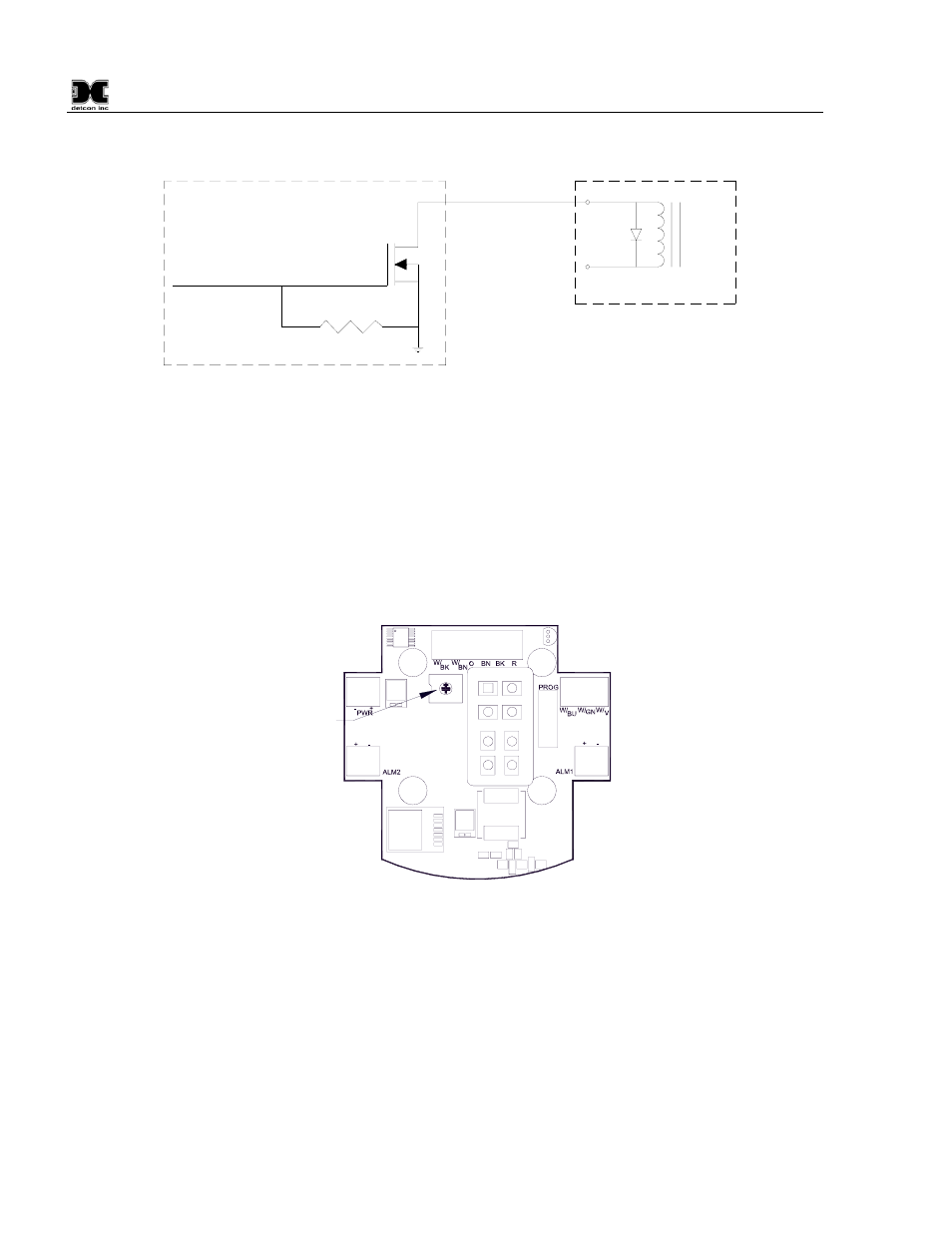
Detcon alarm terminal boards are available that allow either AC or DC/Battery operation with the relays built
onto the board. These boards provide a complete solution to connecting an RXT-300 to power and providing
high-current relay closures. Figure 13 shows as an example, the DC/Battery Alarm board that take two of the
four RXT-300 Alarm outputs and generates two 24VDC outputs to drive audio and/or visual alarms. Any two
of the four Alarm outputs can be used and will be based on how alarms are configured for the system. This
board is designed to operate off of the 12VDC Detcon Smart Battery pack.
Alarm 2
Wiring
Alarm 1
Wiring
Wiring to/from
Transceiver
Wiring to/from
Transceiver
External
24VDC
Connections
Rotary Switch
for Modbus
Address
012
3
4
5
678
9A
B
C
D
EF
Figure 13 DC/Battery Alarm Board
2.3.4 4-20mA A & B
The RXT-300 supports up to two 4-20mA signal inputs (A and B) used for monitoring 4-20mA devices (See
Figure 14). For the primary 4-20mA signal input, use A (green wire). For the secondary 4-20mA signal input,
use B (yellow wire). The input values are continuously read by the RXT-300 and stored in registers accessible
locally through two Modbus™ registers. During system configuration, these registers can be assigned to
sensors and the RXT-300 will then monitor and report on any alarm conditions.
Readings on a 4-20mA input are converted to representative values, for example, 4mA is read as a value of
400 and 20mA is read as a value of 2000. These inputs present a load of 162 ohms to ground so a current of
20mA will develop around 3.4V across the input and ground. This will consume a third less power versus the
250 ohm load used in other implementations. The inputs are protected for voltages up to 30V but the input