5 electrical installation, Figure 10 typical installation, Drain conduit "t" eys seal fitting – Detcon FP-524D-HRT User Manual
Page 12
Model FP-524D-HRT
FP-524D-HRT Instruction Manual
Rev. 0.1
Page 8 of 48
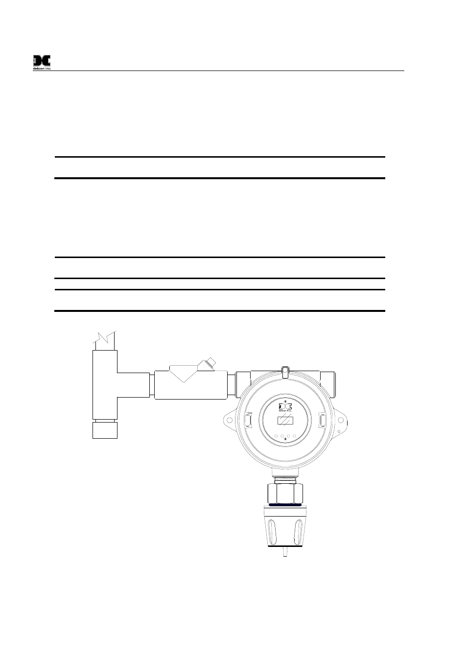
2.5 Electrical Installation
The Sensor Assembly should be installed in accordance with local electrical codes. The sensor assemblies are
CSA/NRTL approved (US and Canada) for Class I, Division 1, Groups B, C, & D area classifications.
Proper electrical installation of the gas sensor is critical for conformance to Electrical Codes and to avoid
damage due to water leakage. Refer to Figure 10 and Figure 11 for proper electrical installation.
NOTE: If a conduit run exits the secondary port, repeat the installation technique shown in
Figure 10.
In Figure 10, the drain allows H
2
O condensation inside the conduit run to safely drain away from the sensor
assembly. The electrical seal fitting is required to meet the National Electrical Code per NEC Article 500-3d
(or Canadian Electrical Code Handbook Part 1 Section 18-154). Requirements for locations of electrical seals
are covered under NEC Article 501-5. Electrical seals also act as a secondary seal to prevent water from
entering the wiring terminal enclosure. However, they are not designed to provide an absolute watertight seal,
especially when used in the vertical orientation.
NOTE: A conduit seal is typically required to be located within 18" of the J-Box and Sensor
Assembly. Crouse Hinds type EYS2, EYD2 or equivalent are suitable for this purpose.
NOTE: The Detcon Warranty does not cover water damage resulting from water leaking into
the enclosure.
Drain
Conduit
"T"
EYS Seal Fitting
PGM
1
PGM
2
MODEL
FP-524D
HOUSTON, TEXAS
FLT
1
2
CAL
MicroSafe
LEL Gas Sensor
ALM ALM
TM
Figure 10 Typical Installation