2 back panel – Aposonic A-S0402R21 User Manual
Page 9
- 9 -
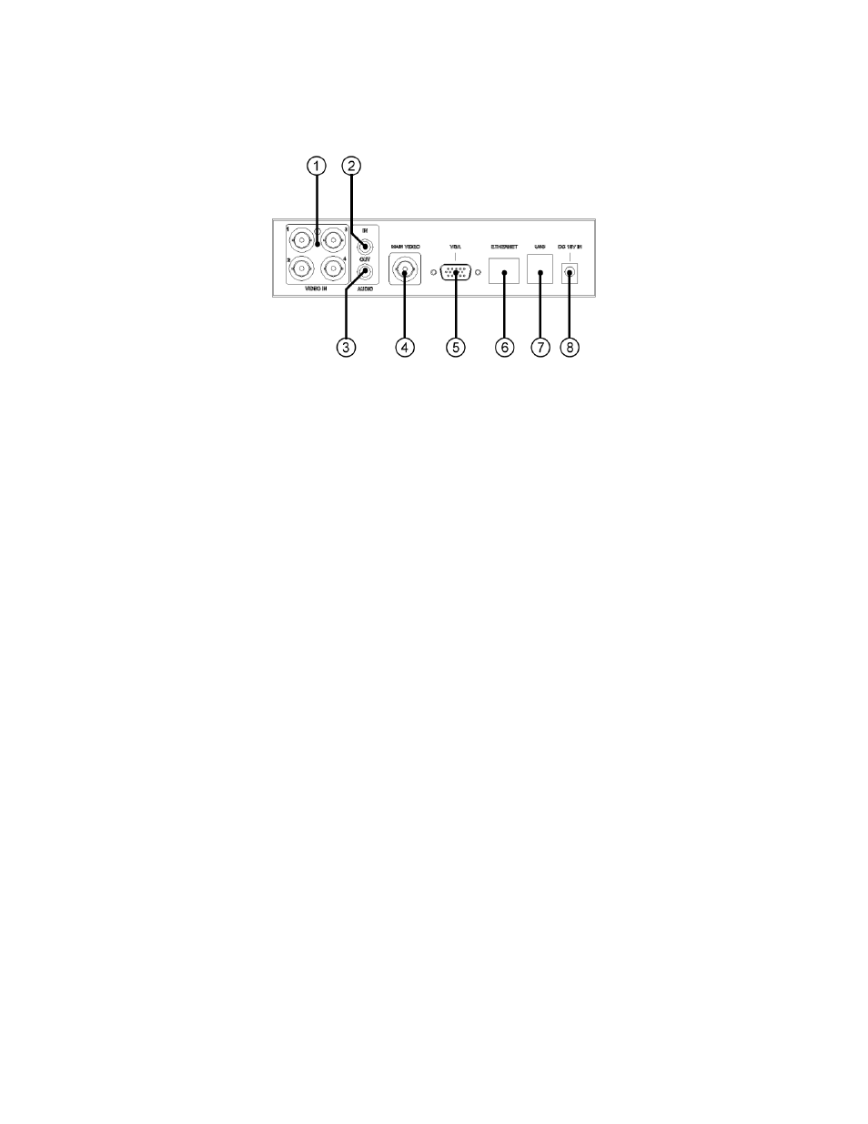
2.2 Back Panel
1. Video Input Connectors (1-4)
Connect system cameras to these BNC connectors. The internal
75Ω
termination is always ON.
2. Audio Input Connectors (AUDIO IN)
The RCA connector accepts line-in audio signal supplied from external
devices such as microphone amplifiers.
3. Audio Output Connectors (AUDIO OUT)
The connector supplies line-out audio signal to external devices such as
speakers. Recorded audio will be supplied from AUDIO OUT during
playback.
4. Main Video Output Connectors (MAIN VIDEO)
Connect TV monitors to the BNC connector for main monitor display.
5. VGA Connector (VGA)
Connect VGA monitor to the D-SUB 15-pin female connector for main
monitor display.
6. Ethernet Connector
Connect this unit to a 10/100Base-T Ethernet network through this port.
7. USB2.0 Connectors (USB)
Connect the lower one of the USB 2.0 connectors to USB mouse.
Connect the upper USB 2.0 connector to USB 2.0 compatible device, such
as USB 2.0 disk drive, DVD+RW, USB 3G dongle, etc.
8. Power Cord Inlet (DC 12V IN)
Connect to DC +12V power source.