6 installing desiccant – Van Air Systems PLD 8-7.2 / 36-7.2 User Manual
Page 4
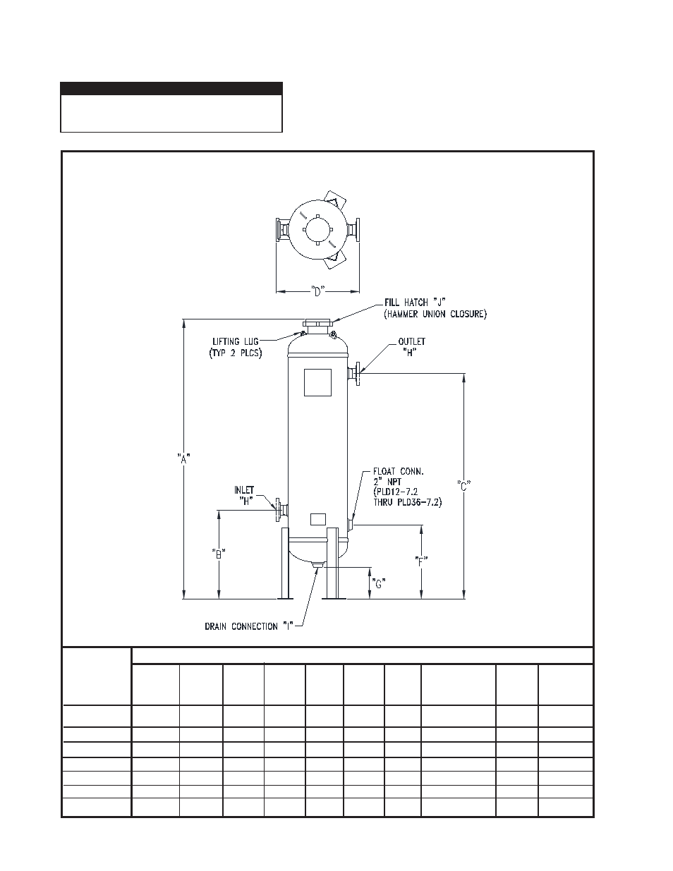
FIGURE 2-B DIMENSIONS
PAGE 4
Open fi ll cover and add the proper amount of pre-bed material and
desiccant to fi ll the dehydrator to the MAXIMUM LEVEL; then level off
the top off the bed. (Reference SECTION 4.3 for desiccant
installation instructions)
USE VAN GAS ABSORBENT DESICCANT ONLY!
Close fi ll cover. Make sure that the inlet and outlet shut-off valves,
and manual drain valve are closed.
2.6 INSTALLING DESICCANT
MODEL
PLD 8-7.2
PLD 12-7.2
PLD 16-7.2
PLD 20-7.2
PLD 24-7.2
PLD 30-7.2
PLD 36-7.2
DRYER DIMENSIONS-
INCHES
H
Inlet
/Outlet
2" NPT
2" NPT
2" NPT
2" NPT
3" RF FLG 300#
3" RF FLG 300#
3" RF FLG 300#
C
Outlet
Height
54-13/16"
76"
76"
76"
71-5/8"
75-1/2"
76-3/16"
D
In to Out
Width
13-1/8"
15-3/4"
19-1/4"
23-1/4"
36"
42
49-3/4"
E
Outside
Dia.
8-5/8"
12-3/4"
16"
20"
24"
30"
37-3/4"
F
Float
Height
N/A
25"
25"
25"
21-1/8"
25"
25-11/16"
G
Drain
Height
2-9/16"
13-9/16"
12-7/8"
11-7/8"
6-3/16"
8-7/16"
7-1/8"
A
Overall
Height
70"
94-3/8"
95-1/4"
94-3/4"
93-1/8"
98-5/16"
100-13/16"
B
Inlet
Height
13-13/16"
30"
30"
30"
26-1/8"
30"
30-11/16"
I
Drain
1" NPT
2" NPT
2" NPT
2" NPT
2" NPT
2" NPT
2" NPT
DEPRESSURIZE DEHYDRATOR COMPLETELY
BEFORE ATTEMPTING TO REMOVE FILL COVER.
IMPORTANT
J
HAMMER
UNION
4"
4"
4"
6"
6"
6"
6"