0 installation, 0 purpose, Maximum capacities - mscfd – Van Air Systems PLD 8-7.2 / 36-7.2 User Manual
Page 2: 1 location
MODEL
NO.
PLD 8-7.2
PLD 12-7.2
PLD 16-7.2
PLD 20-7.2
PLD 24-7.2
PLD 30-7.2
PLD 36-7.2
PAGE 2
2.0 INSTALLATION
CAPACITY: The chart below indicates the maximum fl ow rate
through the dehydrator for a 24 HOUR period. To calculate the
capacity for a rate per minute just multiply the MSCFD RATE (from
chart ) by 0.6944 example:
A PLD 12-7.2 operating at 100 PSIG has a maximum MSCFD rate
of 132. To fi gure the SCFM multiply 132 MSCFD x 0.6944 which
equals 92 SCFM
NOTE: This is the MAX instantanious fl ow that
can be processed through the dehydrator without
deterioration of the drying performance.
OPERATING PRESSURE: More gas can be processed through the
dehydrator at higher pressures. Locate the dehydrator at the highest
practical pressure, but do not exceed the maximum rated working
pressure of the dehydrator. Refer to the capacity chart located below.
AFTERCOOLING: If the gas being processed has been compressed
mechanically, an aftercooler, fi nned tubing or extended run of piping
will usually be necessary to reduce the inlet gas temperature to the
dehydrator.
MAXIMUM CAPACITIES - MSCFD
1,000 STANDARD CUBIC FEET PER DAY
600 PSIG
377
709
1108
1778
2522
4001
6385
500 PSIG
315
594
928
1489
2112
3350
5346
400 PSIG
254
479
748
1200
1701
2700
4307
300 PSIG
193
363
567
910
1291
2049
3269
200 PSIG
132
248
387
621
881
1398
2230
100 PSIG
70
132
207
332
471
747
1191
MAXIMUM
WORKING
PRESSURE
720 PSIG
720 PSIG
720 PSIG
720 PSIG
720 PSIG
720 PSIG
720 PSIG
PART
NO.
80-1326
80-1328
80-1330
80-1332
80-1334
80-1466
80-1308
720 PSIG
450
848
1325
2126
3014
4783
7631
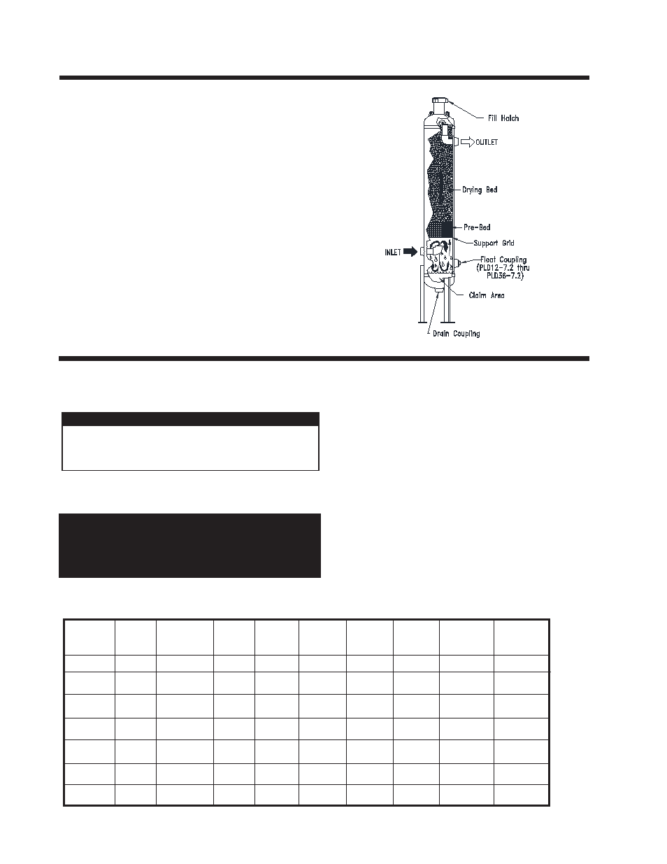
1.0 PURPOSE
A Pipeline Dehydrator removes the water vapor (humidity) pres-
ent in the gas stream. The process cleans and dries the gas as it
fl ows through a vessel which is fi lled with a special drying agent
(desiccant). The dehydrator operates automatically. There are no
moving parts and no external source of power is required.
"Wet" natural gas enters the lower portion of the dryer where liquid
water and solid particles are separated by gravity and fall to the
bottom of the vessel. The gas moves upward through the prebed
and drying bed of Van Gas desiccant tablets. The tablets attract
and absorb moisture from the gas as it fl ows through the desiccant
bed. The tablets dissolve gradually as they absorb the moisture
and the liquid falls to the bottom of the vessel. The liquid run off in
the prebed creates an extended surface area capable of removing
additional moisture from the gas. This conserves the absorbent
desiccant tablets. The "dry" natural gas fl ows through the dryer
outlet.
The solution of dissolved desiccant and water that falls into the
claim area at the bottom of the vessel must be drained regularly to
prevent the vessel from fl ooding. An automatic drain valve can be
installed to prevent the vessel from fl ooding.
2.1 LOCATION
The ability of a dehydrator to dry natural gas is dependent on
the correct location of the unit. Temperature and pressure are
the keys to selecting the proper location.
INLET GAS TEMPERATURE: Lower inlet gas temperatures will
result in a lower moisture content at the outlet of the dehydrator.
Locate the dehydrator at the point where temperature is the lowest.
ALWAYS PROCESS THE GAS THROUGH THE
DEHYDRATOR AT THE LOWEST TEMPERATURE
AND THE HIGHEST PRESSURE.
IMPORTANT
CAUTION
The gas temperature should not exceed:
100°F for GASDRY PRIME
80°F for GASDRY PEAK
100°F for GASDRY MAX