3 inlet and outlet piping, 4 afterfilter, 5 drain valve – Van Air Systems PLD 8-7.2 / 36-7.2 User Manual
Page 3: 2 piping and ancillary equipment
PAGE 3
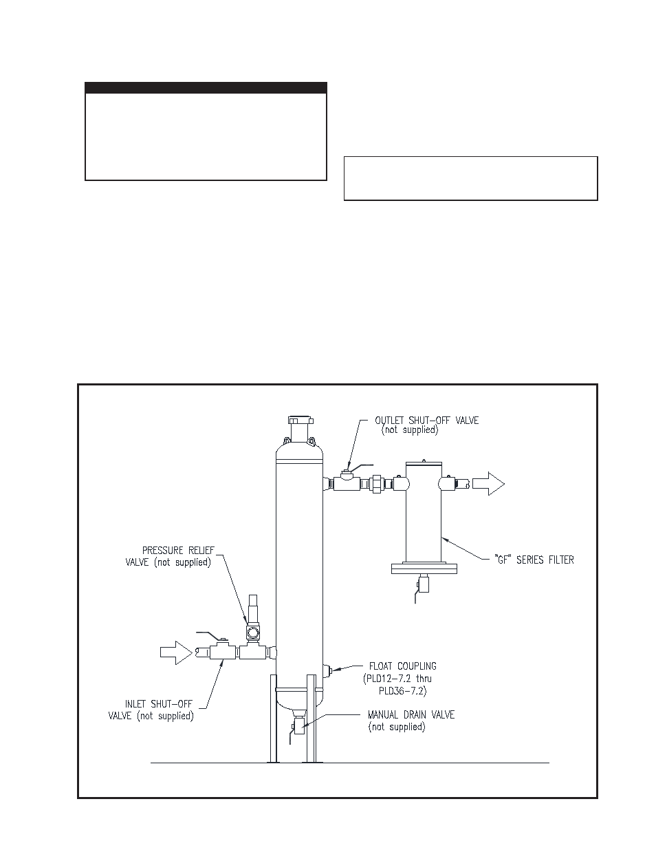
FIGURE 2-A RECOMMENDED INSTALLATION
2.3 INLET AND OUTLET PIPING
NOTE
Inlet and outlet shut-off valves will make start-up
and addition of desiccant easier.
Two shut-off valves should be installed (not furnished with
dehydrator)-one at dryer inlet and another at dryer outlet. See
Figure 2-A Recommended Installation.
Connect the inlet and outlet piping as shown in Figure 2-A.
2.4 AFTERFILTER
Van Gas "GF" Series Filters can be installed downstream of the
dehydrator to remove particulate contamination from the natural
gas. Contact Van Gas for details.
2.5 DRAIN VALVE
Install a drain valve (not furnished with dehydrator) in the drain
coupling at the bottom of the tower (except on PLD8-7.2). A fl oat/
auto drain valve system is available. Contact Van Gas for details.
IMPORTANT
COMPLY WITH ALL FEDERAL, STATE, AND
LOCAL REGULATIONS CONCERNING
INSTALLATION OF NATURAL GAS SYSTEMS.
COMPLIANCE TO AND KNOWLEDGE OF ALL
REGULATIONS IS THE RESPONSIBILITY OF
THE INSTALLER.
Install a pressure relief valve in the up-stream piping (relief
valve not furnished). A relief valve must be installed to
conform with the ASME Boiler and Presssure Vessel Codes,
Section VIII, Division 1 UG-125, Paragraph (1) and OSHA
standards. Also comply with all applicable Federal, State,
and Local codes.
2.2 PIPING AND ANCILLARY EQUIPMENT
Make sure that the temperature of gas is not over the maximum
for the desiccant being used. If gas temperature is too high, cool it
prior to the dehydrator.
Mount the dehydrator on a level surface capable of supporting the
weight of the vessel, such as a cement pad or a skid.