Van Air Systems FR-800 User Manual
Page 8
PAGE 8
6.4 DRYER CONTROLS
The control is housed in a NEMA 4X enclosure and it has the following
features:
- Power switch
- Power On light
- Fail to Switch light
- Alarm Reset pushbutton
- Hour Meter
See
Figure 6B for control box door.
6.4-2 SWITCHING FAILURE:
When there is a switching failure (failure of control solenoid valves
SV1 & SV2; failure of exhaust valve to open; or clogging of exhaust
muffler), the Fail to Switch LED will be lit. This will energize the
Alarm Contacts shown in
FIGURE 10D. The contacts can be wired
for remote annunciation. To reset the Switching Failure Alarm press
the Alarm Reset Pushbutton on the front of the control box. If the
condition causing the alarm is not corrected, the alarm will
re-activate in 90 seconds.
6.3 MOISTURE INDICATOR
The moisture indicator is in the center of the panel. The moisture
indicator is a clear plastic tube filled with moisture sensing crystals. A
sample of outlet air is directed through the indicator.
The crystals will change colors from
PINK (indicating wet air) to
BLUE (indicating dry air) as the dew point of the air changes from
+20
O
F to -40
O
F.
OPERATION
SECTION 6
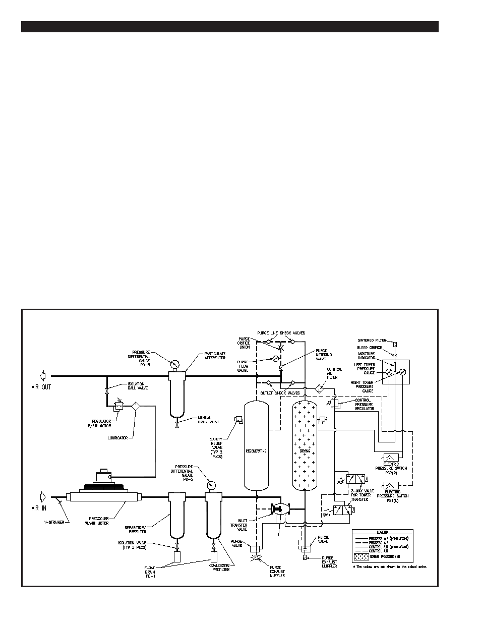
FIGURE 6A PNEUMATIC SCHEMATIC
6.4-1 SMART RELAY:
The dryer cycle is controlled by a SmartRelay, two solenoid valves
and two pressure switches. The dryer timing chart is shown in
FIGURE 6C. The SmartRelay has a battery back-up that will hold
the program in memory safely for 2 years.
6.4-3 HOUR METER:
The Hour Meter is located on the front of the control box. It is used
to log the total number of hours that the Prep-40 dryer system has
been in operation.