Van Air Systems FR-800 User Manual
Page 14
PAGE 14
10.3 CHECKIING THE 3-WAY PILOT VALVES
(SV1 & SV2) TOWER CHANGEOVER
All 3-way pilot valves have manual override buttons on the top of the
valve. To test SV1 and SV2 do the following:
Make sure the dryer system is pressurized and the Power switch
is in the
OFF position. Both towers should be at full line pressure
Pushing the manual override of SV1 should cause the left tower to
depressurize. Allow the left tower to come back up to full line
pressure. Pushing the manual override of SV2 should cause the
right tower to depressurize. If this does not happen, replace that
solenoid valve.
With the Power switch (SW) in the
ON position and the dryer system
pressurized, monitor the dryer system for one complete cycle. SV1
should be activated when the left tower is in the regeneration stage
(depressurized) from 15 seconds to 5 minutes. SV2 should be
activated when the right tower is in the regeneration stage
(depressurized) from 5 minutes and 15 seconds to 10 minutes.
These two operations can be monitored in one 10 minute cycle.
Reference
FIGURE 6C for dryer timing chart.
If the above responses are not observed, first check to see if power
is being supplied to each solenoid valve when it is supposed to
open. Check the wiring between the SmartRelay and solenoid
valves. If the SmartRelay is not supplying power to the valve as it
should, replace the SmartRelay. If the valve has power but does not
operate, it must be replaced.
OUTPUT DEVICES
Q1 SV1
Q2 SV2
Q3 PL2
Q4 ALARM CONTACT
TROUBLESHOOTING
SECTION 10
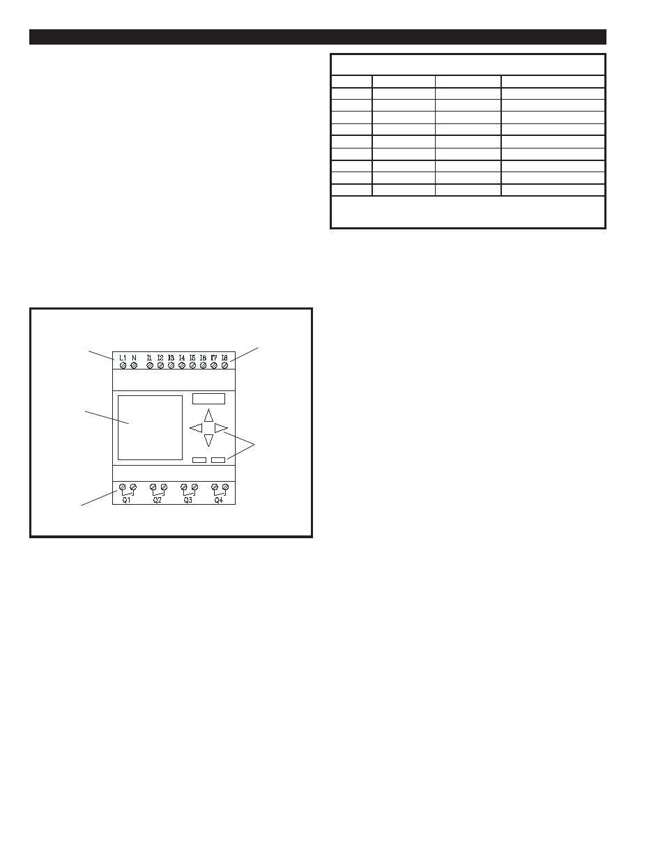
FIGURE 10A SMART RELAY DETAIL
FIGURE 10B INPUT AND OUTPUT LIST
INPUT DEVICES
I1
PS1
I2
PS2
I3
ARPB
I4
SPARE
I5
SPARE
I6
SPARE
I7
SPARE
I8
SPARE
NOTE:
The general alarm contact is a normally open dry contact which is wired to terminals #16
and #17.
10.2A TESTING THE INPUT DEVICES
The input devices supply a 120VAC signal to the SmartRelay. See
FIGURE 10B for a list of the input devices.
The input devices can be easily tested for proper operation. With
power to the control box, set the Power switch to the ON position.
Press the Alarm Reset Pushbutton and verify that there is
120VAC between terminals N and I3 on the Smart Relay. If there
is no voltage, replace the Alarm Reset Pushbutton.
The pressure switches monitor the failure to switch option. The
inputs from the pressure switches (PS1, PS2) can be observed
while the dryer system is in operation. Any time there is more
than 30 psig pressure in the left tower, pressure switch (PS1)
should supply a 120VAC signal to Smart Relay terminal I1. Any
time there is more than 30 psig pressure in the right tower,
pressure switch (PS2) should supply a 120VAC signal to S
martRelay termial I2. If either of the pressure switches does not
respond as previously explained, check the wiring to the pressure
switch. If the wiring and device are good, theSmartRelay is faulty
and should be replaced. Reference
FIGURE 10D WIRING
DIAGRAM for wiring and terminal numbers.
10.2B TESTING THE OUTPUT DEVICES
The SmartRelay’s outputs are 120VAC. See
FIGURE 10B for a
list of the dryer system output devices.
To check output devices SV1 and SV2, follow the procedure in
SECTION 10.3.
INPUTS
POWER
LCD
DISPLAY
CONTROL
BUTTONS
OUTPUTS
10-2 CHECKING THE SMARTRELAY
The control system consists of three different control systems:
1. The SmartRelay
2. Input devices (120VAC components)
a. Pressure switches
b. Alarm Reset push-button
d. Power switch
3. Output components
a. Pilot valves
b. Lights
c. General alarm contact
The SmartRelay controls the cycling of the dryer system. The
program logic is stored on an electrically erasable non-volatile EE-
PROM. Loss of power will not cause loss of the program.
If the LCD display on the SmartRelay is not lit, the SmartRealy is not
operating. If this occurs, check fuse 1FU and replace as needed.
If there is power to the SmartRelay and is still does not function,
consult factory.
See
SECTION 10.2A and 10.2B for procedures to verify the
operation of the input and output devices.