Van Air Systems FR-800 User Manual
Page 6
PAGE 6
5.5 CONDITIONING THE DESICCANT BED
To condition the desiccant bed, the dryer system is operated without any
outlet flow while the towers regenerate with purge air.
Observe the dryer system for several cycles to make sure that it is
operating properly.
At initial start up or after extended shutdowns (over one month), the
dryer system may take 24 to 48 hours of continuous operation for the
bed to be conditioned. Moisture that has accumulated on the desiccant
bed should be removed before the dryer system is placed on stream.
Once the moisture indicator on the dryer system turns blue, the desiccant
bed is ready. The Prep-40 dryer is now ready for operation.
START UP
SECTION 5
5.1 START UP
WARNING
BEFORE STARTING THIS DRYER SYSTEM, FOLLOW THE
INSTALLATION INSTRUCTIONS AND PROCEDURES COMPLETELY.
SERIOUS PERSONAL INJURY CAN RESULT IF INSTRUCTIONS ARE
NOT CAREFULLY AND COMPLETELY FOLLOWED.
DO NOT REMOVE, REPAIR, OR REPLACE ANY ITEM ON THIS
DRYER SYSTEM WHILE IT IS PRESSURIZED.
Make sure that the Power switch is in the
OFF position.
If the dryer system is being started up for the first time or after the
desiccant has been changed, the purge mufflers must be removed.
See
SECTION 2.2 for safety precautions concerning the desiccant
dust.
WARNING
WHEN OPERATING THIS DRYER SYSTEM WITHOUT THE
MUFFLERS INSTALLED, USE HEARING PROTECTION.
Pressurize the air system.
Place the Power switch in the
ON position. One tower will already be
pressurized. The other tower will depressurize. The purge valve on
the tower that is not pressurized will be open, air should be exhausting
from the muffler.
The dryer system is equipped with a purge metering valve. The setting
should be checked per
SECTION 5.2 before placing the dryer system
on stream.
Set the control pressure regulator per
SECTION 5.3.
Set the lubricator and regulator for the pre-cooler air motor per
SECTION 5.4.
Condition the desiccant bed per
SECTION 5.5 before placing the dryer
system on-stream.
Install the purge mufflers per
SECTION 5.6.
5.2 ADJUSTING THE PURGE FLOW
IMPORTANT
NEVER OPERATE THE DRYER SYSTEM WITH THE PURGE
METERING VALVE CLOSED. IF THE VALVE IS CLOSED, THE
TOWERS WILL NOT REPRESSURIZE AND SWITCHING FAILURE
WILL OCCUR.
DO NOT ADJUST THE PURGE METERING VALVE ABOVE OR BELOW
THE RECOMMENDED SETTING FOR THE OPERATING CONDITIONS
OF THIS INSTALLATION. IMPROPER SETTING MAY CAUSE POOR
DRYER SYSTEM PERFORMANCE AND/OR
EXCESSIVE USE OF PROCESS AIR.
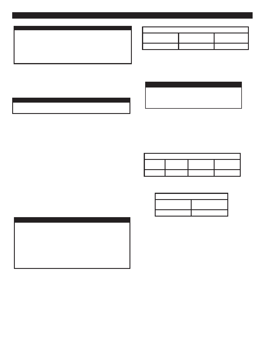
FIGURE 5B REQUIRED PURGE FLOW
DRYER
MODEL
FR-800
PURGE
FLOW
144.0 SCFM
5.3 SETTING THE CONTROL PRESSURE REGULATOR
The control pressure regulator is located in line with the control filter and
it is used to protect the pneumatic control components. This regulator
should be set at 115 PSIG.
CAUTION
DO NOT OPERATE THIS DRYER SYSTEM WITH
THE CONTROL AIR PRESSURE REGULATOR
ABOVE 115 PSIG TO PREVENT DAMAGE TO
THE PNEUMATIC CONTROLS.
5.4 ADJUST THE REGULATOR & LUBRICATOR
The regulator and lubricator for the pre-cooler air motor must be properly
set to ensure trouble-free air motor operation.
The regulator is used to set the speed of the pre-cooler fan. The regulator
is factory set using a tachometer and a clean precooler core. See
FIGURE
5C. As the core becomes dirty, a higher regulator pressure setting may
be required to maintain the fan speed.
Set the lubricator per
FIGURE 5D.
FIGURE 5C FACTORY REGULATOR SETTING
DRYER
MODEL
FR-800
SETTING
(PSIG)
25
FIGURE 5D LUBRICATOR SETTING
DRYER
MODEL
FR-800
DROPS PER
MINUTE
1
FAN SPEED
(RPM)
1725
AIR USAGE
(SCFM)
18
The Prep-40 dryer system is equipped with a purge metering valve and
gauge. Reference
SECTION 3.2 for Location. The gauge indicates the
back pressure on the purge flow orifice, which is in direct correlation to
the purge flow in SCFM.
The purge flow can be adjusted for the operating conditions.
This dryer system was shipped with the purge flow set for the rated inlet
flow at 100 PSIG. Reference
SECTION 3.1 for rated flow. This setting
should be correct for most installations. Before placing the dryer system
on stream, check the purge metering valve setting.
FIGURE 5B shows the purge flow, in SCFM, and the pressure setting
required for each model. This flow is required to properly regenerate
the desiccant beds.
PURGE FLOW
GAUGE SETTING
46 PSIG