Triton 9200 Installation Manual User Manual
Page 25
2 5
T
ABLE
-T
OP
I
NSTALLATION
P
ROCEDURES
Fig. 12
Fig. 13
8.
Using two, 1/4” bolts, secure the
SuperScrip using the two remaining
mounting holes on the bottom left-
hand side of the unit.
•
Place one flat washer under the head
of each bolt and place the bolt
through the mounting hole. The
head of the bolt will be inside the
unit. (Figure 14)
•
From underneath the mounting sur-
face, place a flat washer, then a lock
washer and finally a nut on each
bolt. Tighten down with the 7/16”
socket and ratchet wrench. (Figure
9)
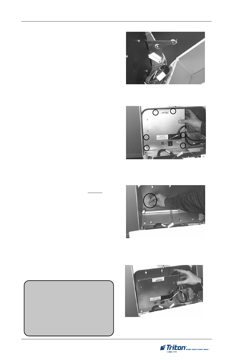
9.
Re-install the power supply. Place
the power supply module in the
SuperScrip enclosure. (Figure 15)
Secure the module in place using the
six screws removed in Step 7. En-
sure the left stay arm is re-attached.
Re-connect the data cable to the ap-
propriate connector on the power
supply.
Fig. 14
Fig. 15
10. Close the SuperScrip and lock the
unit using the security key. Connect
the AC power and telephone cables
to the appropriate receptacles and
complete the unit setup, as needed.
Ensure the unit is operating normally.
**IMPORTANT**
1. AC power for the terminal should
come from a dedicated source with an
isolated ground.
2. The phone line used for the terminal
shall not be shared with any other de-
vice!