Triton 9200 Installation Manual User Manual
Page 24
2 4
M
ODEL
9200 (S
UPER
S
CRIP
) I
NSTALLATION
G
UIDE
Fig. 8
OPTIONAL STEPS (7-9)
At this point, the SuperScrip unit has
been secured on the right side. This
may be sufficient for your application.
If so, you can skip Steps 7-9, which
involve removing the power supply in
order to access the mounting holes on
the left side of the unit. Go directly to
Step 10, which concludes the installa-
tion procedure by closing, locking and
placing the unit in service.
Fig. 9
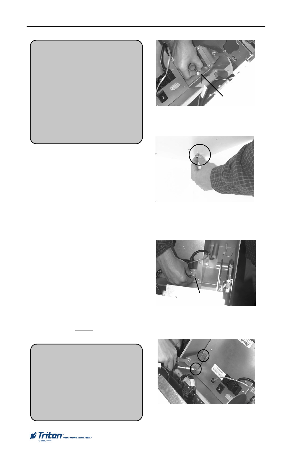
7.
To access the remaining two mount-
ing holes you must remove the
unit’s power supply. Follow these
steps to remove the power supply
assembly:
•
Disconnect the data cable at the
power supply. (Figure 10)
•
Remove the six power supply mount-
ing screws using the #2 Phillips
screwdriver. Note that two of these
screws also secure the left stay arm
to the power supply. (Figures 11
and 13)
•
Move the left stay out of the way.
(Figure 12)
•
Lift the power supply out of the unit.
(Figure 13) Caution: Unit may tip
foward if not previously secured as
directed in Step 6. Place the power
supply to the side.
Fig. 10
Fig. 11
Data cable
**WARNING**
This unit may be equipped with more
than one power cord. Disconnect All
power cords prior to servicing!
For continued fault protection, follow
the correct voltage and current ratings
when replacing any fuses.