Triton 9200 Installation Manual User Manual
Page 23
2 3
T
ABLE
-T
OP
I
NSTALLATION
P
ROCEDURES
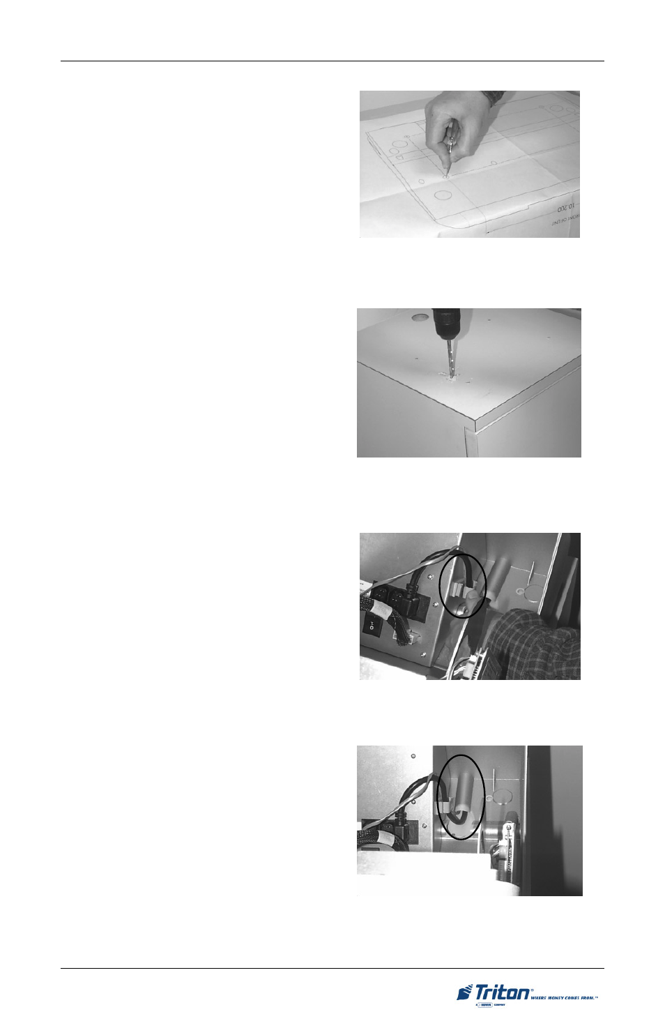
3.
Use the center punch (or equivalent)
to mark the drilling points as indi-
cated on the template. Remove the
template. (Figure 4)
4.
Drill the four mounting holes at the
locations marked in Step 3, using the
3/8” drill bit and electric drill. (Fig-
ure 5)
Fig. 4
Fig. 5
5.
Place the SuperScrip on the mount-
ing surface. Perform the following
steps:
•
Open the unit using the enclosure
security key,
•
Locate the power and telephone
cables. Uncoil these cables. Care-
fully tilt the unit foward and route
the cables through the snap con-
nector on the side of the power sup-
ply housing. (Figure 6)
•
Route the cables through the se-
lected channel (rear channel shown
in Figure 7) Leave some slack in the
cables.
6.
Using two, 1/4” Bolts, secure the
SuperScrip using the two mounting
holes on the bottom right-hand side
of the unit.
•
Place one flat washer under the head
of each bolt and place the bolt
through the mounting hole. The
head of the bolt will be inside the
unit. (Figure 8)
•
From underneath the mounting sur-
face, place a flat washer, then a lock
washer and finally a nut on each
bolt.Tighten down with the 7/16”
socket and ratchet wrench. (Fig-
ure 9)
Fig. 6
Fig. 7