Triton 9200 Installation Manual User Manual
Page 20
2 0
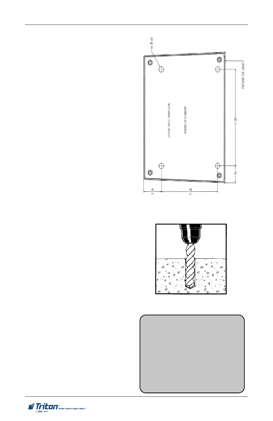
Use a center punch tool (or equivalent)
to mark the center of each mounting hole,
as indicated on the template. Use a felt-
tip pen or other marker to carefully mark
the front corners of the cabinet. These
marks will serve as guides to align the
cabinet in the final mounting position.
Remove the template. Figure 5 provides
an example (not to scale) of the template.
Alternative Method. Move the pedestal
to the location where it will be installed.
Locate the four anchor-bolt holes in the
bottom of the cabinet (see Figure 4). Use
a felt-tip pen or other marker to carefully
mark the center of each of these four holes
on the floor and the front corners of the
cabinet. These marks will serve as guides
to align the cabinet properly when it is
moved into the final mounting position.
Move the pedestal aside, to provide clear
access to the mounting hole marks.
4. Drill mounting holes. Drill four (4)
3/8" holes, at least two inches deep,
into the concrete flooring at the ped-
estal base locations marked previ-
ously. Use the 3/8" drill bit and elec-
tric drill. (Figure 6) Use a portable
vacuum cleaner to remove any dust
or debris that may have accumulated
in the holes.
5. Bolt pedestal down. Move the pe-
destal back into position for mount-
ing. Align the mounting hole cut-
outs in the pedestal floor with the
mounting holes. Insert a 3/8" Ex-
pansion bolt through a washer and
into each mounting hole. Firmly
tighten the bolts down to secure the
pedestal to the floor.
Fig. 6. Drill anchor hole.
Fig. 5. Anchor template.(Not to scale)
M
ODEL
9200 (S
UPER
S
CRIP
) I
NSTALLATION
G
UIDE
**WARNING**
This unit may be equipped with more
than one power cord. Disconnect All
power cords prior to servicing!
For continued fault protection, follow
the correct voltage and current ratings
when replacing any fuses.