Tele vue – Tele Vue Panoramic Sky Tour Mount User Manual
Page 2
Tele Vue
V i s i o n a r y
32 Elkay Dr., Chester, New York 10918 (845) 469-4551 www.televue.com
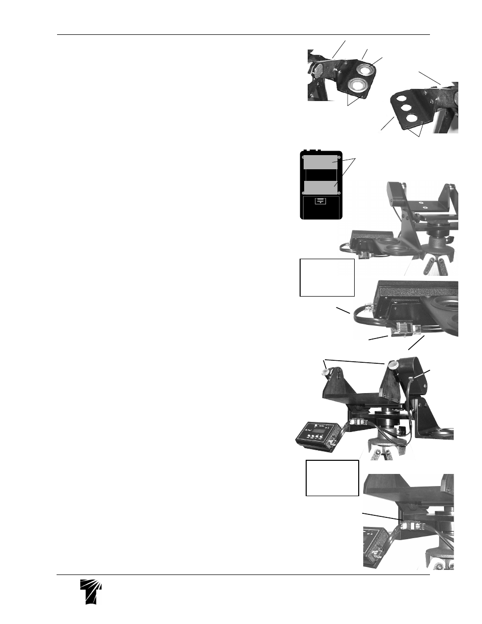
6) Installing Mount Handle
Installing Mount Handle
Installing Mount Handle
Installing Mount Handle
Installing Mount Handle - Follow instructions packaged with handle.
7) Caddy Set Installation
Caddy Set Installation
Caddy Set Installation
Caddy Set Installation
Caddy Set Installation - Attach each Caddy bracket by passing the screws
through the clearance holes in the yoke arms and fixing the thumb knob tight. The
angled edge will match the arms, so that when viewing from the telescope eyepiece
position, the three 1¼" holes will be on the left side, while the two 2" holes with
removable 1¼" plastic plugs will be to your right.
8) Sky Tour Caddy Plate Installation and Computer Attachment
Sky Tour Caddy Plate Installation and Computer Attachment
Sky Tour Caddy Plate Installation and Computer Attachment
Sky Tour Caddy Plate Installation and Computer Attachment
Sky Tour Caddy Plate Installation and Computer Attachment - The Sky Tour
Caddy Plate attaches to either the left or right eyepiece caddy using the two
supplied button head screws and Allen wrench. Keep the two halves of the Velcro
strip together and stick one side on the back of your Sky Tour computer as shown.
Peel the remaining backing off of the Velcro and stick the Sky Tour computer onto
the Mounting Bracket. When using shorter scopes like our Tele Vue-76 or Tele Vue-
85, make sure you leave enough finger room between the computer and the
focuser knob.
9) Sky Tour Wiring Connections
Sky Tour Wiring Connections
Sky Tour Wiring Connections
Sky Tour Wiring Connections
Sky Tour Wiring Connections
a) If the Sky Tour Caddy Plate is attached to the right Caddy, use the Velcro to stick
the Harness Junction Box to the back of the plate, in the lower right hand corner.
Orient the Box so that the Main Wiring Harness plugs straight in from the left end of
the box. The Pigtail Harness will then plug in from the front. Loop the Pigtail around
and plug it into the Sky Tour Computer.
or
b) If the Plate is attached to the left Caddy, use the Velcro to stick the Harness
Junction Box to the underside of the mount head, in the left corner, against the left
side Caddy Bracket. Orient the Box so that the Main Wiring Harness plugs straight
in from the right end of the box. The Pigtail Harness will then plug into the Box
directly toward you. Plug the other end into the Sky Tour Computer.
Telescope Attachment
1) Thread the two studs into the two end holes on the bottom of your telescope
mount ring. Snug tight using the supplied 1/8" Allen key.
2) With the cradle approximately level, set the scope down within it so that the
studs pass through the clearance holes and the telescope's eyepiece end is
closer to the Altitude Tension Knobs.
3) Lock the scope down with the supplied wing nuts.
Telescope Use
1) Place eyepiece in scope.
2) Apply slight and equal tension to altitude bearings using the altitude bearing
tension knobs.
3) Swing the scope up approximately 45° and check balance. If the scope wants
to swing back down, slide the scope back in the mount ring until balance is
achieved. If the scope wants to swing up, push it forward until balance is
achieved.
4) Apply more tension to achieve the desired feel. Extra tension can be used to
overcome a minor out-of-balance condition. However, excessive tension will
cause the movement to be “jerky.” Severe overtightening could strip the threads in
the mount head. Azimuth tension is pre-set at the factory and should not be
adjusted.
5) The most stable way of slewing your scope is by grasping a fixed part of the
telescope, (i.e., focuser body), mount head or (optional) mount handle. Slewing the
scope by holding the diagonal could cause slight image shift when you release.
Computer Alignment
Please follow the alignment instructions on page 11 in the yellow Sky Tour
Operating Guide. Though the guide was originally written for the Gibraltar
Mount, all aspects of Sky Tour use apply to Tele-Pod and Panoramic mounts.
Close-up of junction box
location and orientation
Right handed instal-
lation on Sky Tour
Caddy Plate as
viewed from in front
of the mount
Pigtail
Main Wiring Harness
2" Eyepiece Caddy
1¼" Removable Insert
1¼" Eyepiece Caddy
Yoke Arm
Yoke Arm
Sky Tour
Bracket Holes
Sky Tour
Bracket Holes
Velcro location on
back of Sky Tour.
Left handed
installation on Sky
Tour Caddy Plate
as viewed from
behind the mount
Close-up of
j u n c t i o n
box loca-
tion and
orientation
Altitude
Encoder
Jack
Altitude Tension
Knobs