Tele Vue Tele-Pod Mount User Manual
Tele vue, Tele-pod mount instructions, Parts check list
32 Elkay Dr., Chester, NY 10918 (845) 469-4551 www.televue.com
Tele Vue
V i s i o n a r y
TELE-POD MOUNT INSTRUCTIONS
INTRODUCTION
Thank you for purchasing the Tele-Pod Mount, a convenient, easy to use, travel mount
for your Tele Vue telescope. The Tele-Pod combines the size, weight and flexibility of a
photo-tripod with the smooth, balanced altitude/azimuth motions of our yoke and cradle
mount head. Tele-Pod is perfect for our lighter weight scopes up to the Tele Vue-76 (up to
the Tele Vue-85 for terrestrial uses). The Tele-Pod Mount can be outfitted with the Sky Tour
computer (SKC-3000 & STN-4001) and Eyepiece Caddy Set (TEC-1018) with optional
Sky Tour Caddy Plate (SCP-1019).
COMPONENTS
The Tele-Pod consists of the mount head (TPH-1016) and tripod (TPT-2017). The head
supports the scope and provides vertical and horizontal motions. It features: smooth op-
erating altitude and azimuth bearings with tension adjustments, Delrin scope stop in case
the objective end accidentally “nose-dives,” and both 3/8-16 and 1/4-20 attachment
holes on the bottom of the azimuth bearing plate.
The tripod supports the head and allows height adjustment of the scope. The tripod legs
have rubber feet. See separate instruction sheet for more features of the tripod. Familiarize
yourself with the call-outs on the assembly photos for easy reference and you will quickly
learn how to put your Tele-Pod to best use.
SET-UP
WARNING: If setting up on a slope, ensure that the tripod legs are extended so that the
head is approximately level with the horizon. Failure to do so could cause the telescope
to tip over! This risk increases when using larger, longer scopes.
1) Thread the two studs into the two end holes on the bottom of the telescope mount ring.
Snug tight using the supplied Allen key.
2) Now on the tripod, loosen top leg clamps.
3) Extend each leg so that the mount head is slightly above the desired height and ap-
proximately level with the horizon.
4) Tighten leg clamps.
5a) Spread all three tripod legs to the first click-stop and the mount head should be at
the desired height.
5b) If you need the head higher, loosen the center column’s height adjustment lock knob
and lift to the desired height. Note that the Tele-Pod’s vibration dampening is best when
the center column is not extended.
6) If you have a mount handle, refer to the handle instructions to attach it to the head.
7) With the cradle approximately level, set the scope down within it so that the studs pass
through the clearance holes.
8) Lock the scope down with the supplied knurled knobs.
9) Note: Mount head can be moved to other Tele Vue tripods or camera tripods by using
the 5/64" Allen to loosen lower set screw on Azimuth bearing plate. Flip over and use
3mm Allen to back off 3 small set screws on flange base. Normally the bearing plate
and flange set screws are tight to prevent unscrewing of mount head as mount is turned
in azimuth. Now unscrew the Tele Pod Head.
USE
1) Place eyepiece in scope.
2) Apply slight and equal tension to altitude bearings using the altitude tension knobs.
3) Swing the scope up approximately 45° and check balance. If the scope wants to
swing down, slide the scope back until balance is achieved. If the scope wants to swing
up, push it forward until balance is achieved.
4) Apply more tension to achieve the desired feel. Extra tension can be used to overcome
a minor out-of-balance condition. However, excessive tension will cause the movement
to be “jerky.” Severe overtightening could strip the threads in the mount head.
5) The basic azimuth tension is set at the factory and should not be readjusted. Should
additional azimuth tension be desired, tighten the azimuth tension knob.
6) The most stable way of slewing your scope is by grasping a fixed part, (i.e. focuser
body) or mount handle. Slewing the scope by the diagonal could cause image shift
when you release.
7) When changing eyepiece, it is advisable to first lock one of the altitude tension screws
tight before removing the eyepiece from the telescope. Once you have changed eyepieces,
loosen that altitude tension screw to resume normal movement.
WARNING: Rotating the Tele-Pod head
while the azimuth tension knob is tightened
could cause the azimuth bearing to unscrew
and separate.
Telescope Attachment Diagram
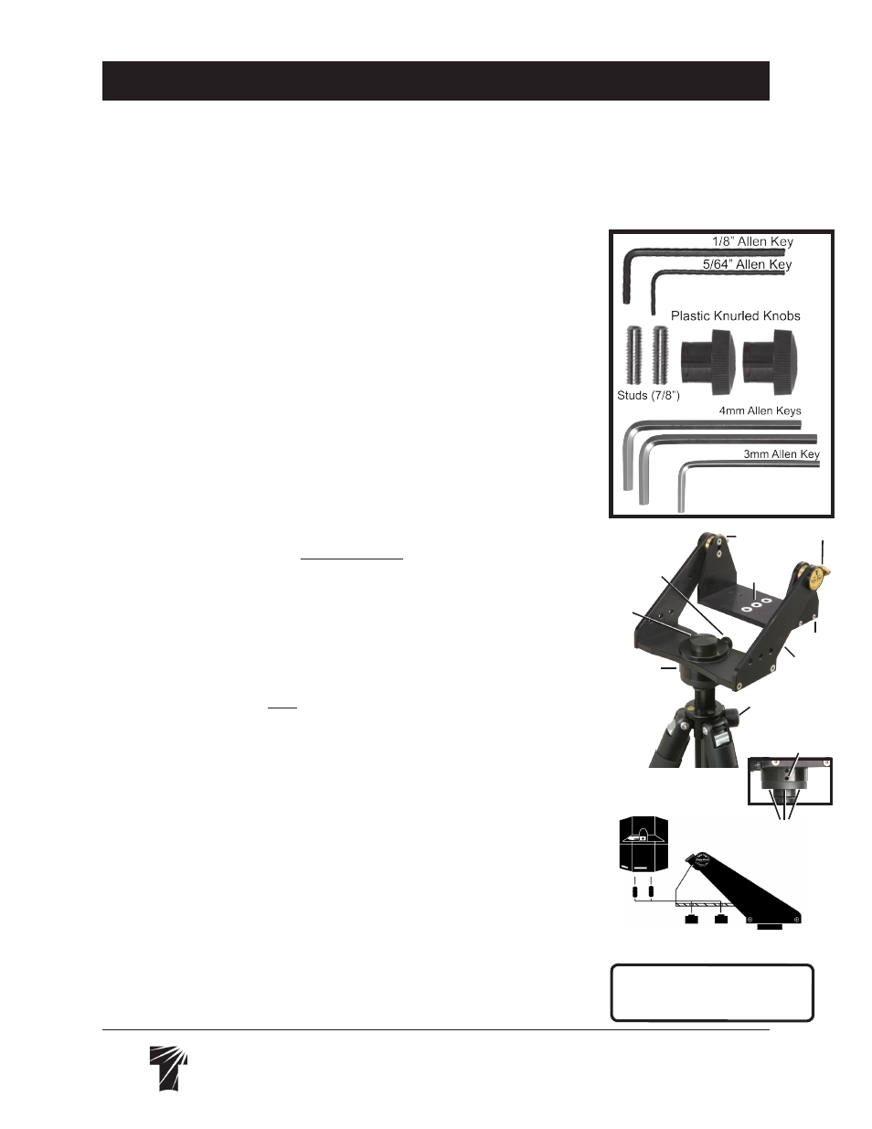
Parts Check List
•Tele-Pod Mount (TPM-2015)
•Mount Handle
•Small-Parts Bag: (2) Studs for scope
attachment, (2) Plastic Knurled Knobs,
(5) Allen Keys: (1) 1/8", (1) 5/64", (1)
3mm, and (2) 4mm
Yoke
Cradle
Altitude Tension Knobs
Stud
Clearance
Holes
Height Adjustment
Lock Knob
Azimuth
Tension
Knob
Azimuth
Bearing Plate
Scope
Stop
Azimuth Bearing Plate
Lower Set Setscrew
Set Screws on
Flange Bottom